Repair Log Seiko TV Watch Receiver TR02-01
 |
| Seiko T001 |
When I first purchased my Seiko TV watch a few years ago, I was able to set up a local TV broadcast and watch video on the watch. This week I pulled it out to test out a new RF modulator and couldn't get a picture no matter what I tried. It would barely even show static.
If you're not familiar, the watch comes in two parts - a receiver box, and the watch itself. The receiver box is basically a compact radio that also happens to tune in TV broadcasts and output video to the watch screen. Given it's age I was not surprised when I opened up the receiver box to find pretty much every single electrolytic capacitor had leaked. The fluid from a failed electrolytic capacitor is corrosive and if left unaddressed it can eat away the copper traces on a PCB. Unfortunately this process had begun by the time I got the board out.
WARNING: the last thing I wish to do is gatekeep, but these receiver units are rare and this repair should not be attempted if you are not sure of what you're doing. There's not a large margin for error here and many of the parts are irreplaceable.
Disassembly:
This was a very elegantly engineered device. There are almost no space tolerances at all which means that it's not very simple to take apart. Thankfully there aren't any screws hidden underneath stickers or anything like that.
1. Start by removing the battery cover and setting it aside


Capacitor Removal:
There are two PCBs inside the receiver, and both use plated through-holes. Under the best of circumstances, plated through-holes are difficult to work with, but when they've been partially corroded by leaked capacitor fluid there're even more fiddly. Solder can't adhere to the oxidized and corroded surface of the metal. When de-soldering, whether you're using a vacuum device or a de-soldering wick, you rely somewhat on capillary action to keep the solder stuck to itself long enough to draw it out. The bits of solder which were exposed to the electrolytic fluid don't melt into the other solder as easily so the components tend to stick in place. Just be patient and keep adding and removing solder until the little buggers let go. Do not use force because the acid in the electrolyte may have weakened the adhesive that holds the copper layer to the PCB and you could damage traces by pushing or pulling.
The PCBs in this receiver do not have a silkscreen, so there are no labels telling you the polarity or position of the capacitors on the PCB itself. This means it's vitally important to take pictures, make notes and double check everything. I sketched a couple of drawings to keep keep track. Since there are no capacitor designations, I just made some up to make it easier.
 |
| Rough sketch of "PCB A" showing capacitor locations, polarity and designations I just made up. |
 |
| Rough sketch of the "Main" PCB showing capacitor locations, polarity and designations I made up because there's no silkscreen. Note "C9" is actually mounted at a 45-degree angle, but the cathode is still on the left. |
The capacitors I've labeled C4, C5 and C6 are underneath the bracket that holds the tuning screw. The tuning screw drives a plastic gear which drives both the red bar that indicates what channel/frequency you're tuning to and the potentiometer that operates the tuner. If the screw is separated from the gear and the gear gets moved, the channel/frequency bar will no longer match what the tuner is actually doing. I decided not to completely remove the bracket to avoid getting these out of alignment, but as a precaution, I moved the dial so the red bar was all the way to the right, and then marked the gear teeth on the potentiometer. I took a photo to remind me of the position.

Cleanup and Trace "Repair"
This is perhaps the first time I have ever opened a device and found that every single one of the electrolytic capacitors had failed and discharged electrolytic fluid. It was not pretty.


The leaky electrolytic fluid had both formed a brown crust in places and had started corroding exposed copper into fuzzy/dusty green rust. The brown crust is fairly easy to remove with a cotton swab and 91% IPA, but the green rust is a little trickier.
The first order of business was to neutralize any remaining acid, so I used a cotton swab to dab the affected areas with a 1:5 dilution of clear ammonia and distilled water. Following that, while observing through a microscope I used a combination of dental pics and scraping tip of an X-acto blade sideways to break off the corrosion and scratch through the oxidation. I followed that up with a fiberglass pen. A good deal of the corrosion had work its way into the vias and through-holes, so I used an extremly fine width tungsten carbide hand drill to gently scrape the corrosion away. When you get the corroded areas back down to bare copper, you'll have a better idea of the extent of the damage and how to proceed with fixing it. It's also a good idea to cover the bare copper with something to discourage oxidation in the future - it doesn't have to be anything fancy, clear nail polish will work fine.
In a couple of cases the traces had been almost completely eaten away, but thankfully there was enough left that I could see where things were supposed to be connected.
Using a DMM, I buzzed out all of the traces to see what was still connected and what wasn't. Unfortunately I did miss one damaged trace during this process which made me have to open everything back up after I put it all back together. I missed it because I only tested continuity from one side of the board and the copper fill between the layers had worn away.
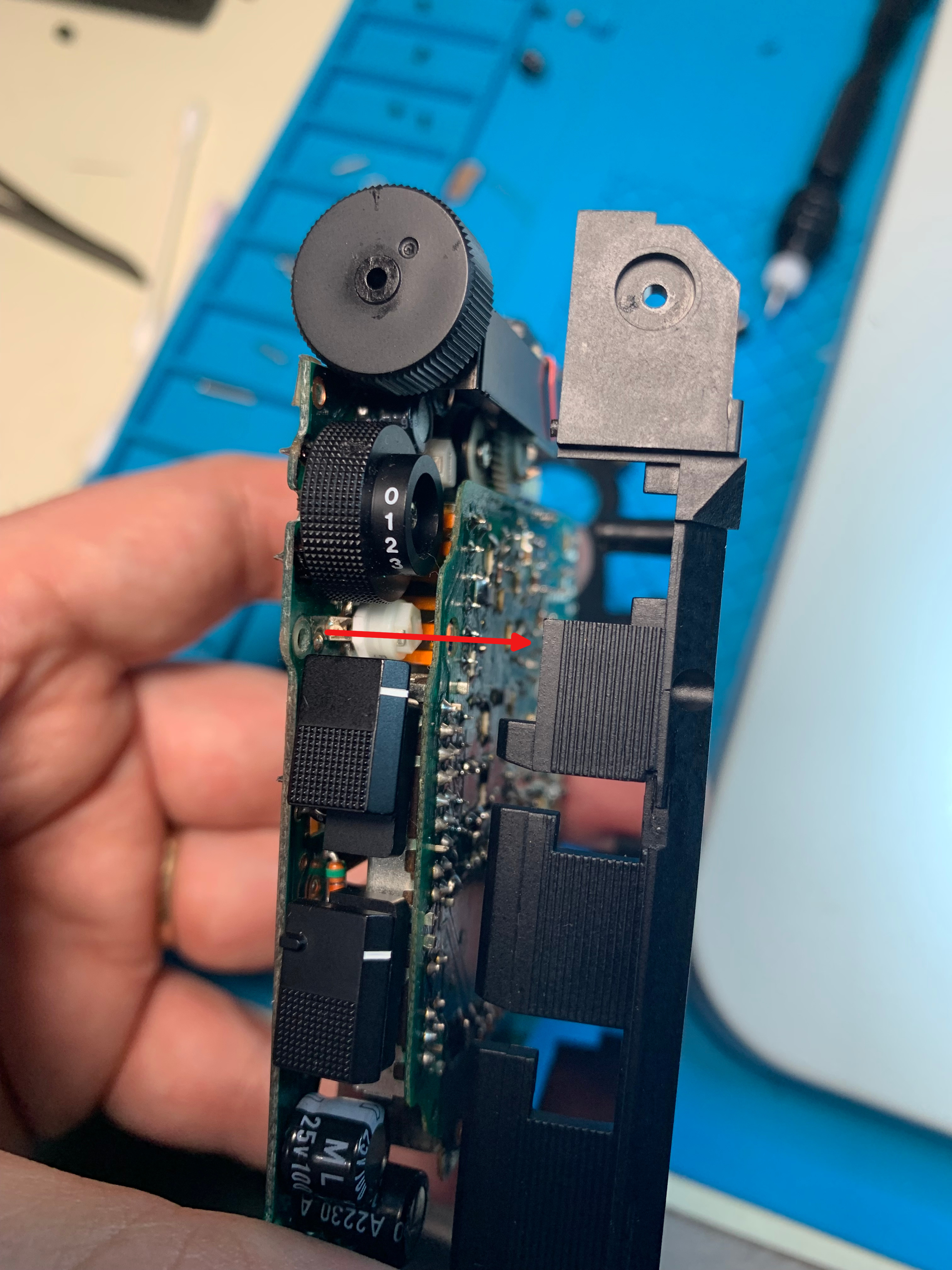
 |
| The circled trace connects the audio capacitor the headphone jack. The ring on the left of the circled area, while obviously damaged is still connected to the trace that leads to the right ring, however the copper pour that connects the left ring to the other side of the board is no longer connected to the ring on this side of the board. |
There are a number of different ways to repair damaged traces. For simplicity sake, I decided to use 32AWG wrapping wire to reconnect the broken connections.


Capacitor Re-installation
As I mentioned earlier, there's almost no space tolerance inside this device. The diameter, length and lead spacing are all just as important as the capacitance and voltage. In case anyone else finds themselves in this position, I've made a chart (again, the designations "C1, C2" etc are just something I made up, but you can scroll up to the sketch to determine the locations):
If you can't find exact matches for these capacitors, you can get away with higher voltage tolerances, smaller diameters and smaller lengths. The lead spacing has to be exact for everything except C1, C15 and C16. You can sometimes get away with larger capacitance values for the power capacitors like C12 and C13, but I do not have the expertise to know when this is safe and when it's not, so stick with the values of the capacitors as you find them.
And lastly, make sure you have a good pair of flush cutters and clip the leads very short when the new capacitors are installed. Even half a millimeter too long and the case will not go back together correctly.
While you're in there...
- Apply a drop of Deoxit to each of the four sliding switches
- Inspect the battery contacts and clean them if necessary. If alcohol will not clear away any discoloration or corrosion, use a rotary tool and a wire wheel. If you needed to use a wire wheel to clear away corrosion, apply some Deoxit to help condition and seal the surface.
- Inspect the barrel plug socket (for the power adapter) and clean if necessary, alcohol and/or a wire wheel. Apply some Deoxit.
Reassembly
- When re-attaching the two PCBs it is crucially important that they be perfectly flat. The black wire that runs along the back may cause the two halves to rock and sit crooked. If you accidentally solder them in that position, you'll have to de-solder and try again - the case will not fit if the two PCBs aren't aligned perfectly.
- When re-installing the black wire pay special attention to the position it lays in across the rear PCB - the wire has to be flat up against the PCB - if it gets routed over top of any components, the case will not close up properly.


- When I attempted to re-install the black wire, it was hard to keep the ground wire from getting uncomfortably close to the leg of the left audio jack, so I put a small strip of Kapton tape underneath the ground wire of the black cable to ensure that they would not touch. It's very hard to see in the image below, so I've outlined where I placed the yellow strip of tape under the black wire.


- I'll mention here again that you have to clip the new component leads very very short or the case will not fit together properly.
- When installing the top "cap" piece over the tuner bar, make sure the switch covers are slid into the same position as the switches themselves.
- When re-installing the ribbon go slowly and do not use much force.
- If any of the screws do not align properly when re-assembling, go back and check that the black wire is not sitting on top of any components, and that your component leads have been trimmed all the way down (can you tell I made these mistakes yet?).
Back in Business


This is really great. Good work!
ReplyDeleteI have a question - any chance you have a service manual or any source of information about the connector wire? I have the watch and receiver, but no cable, and I'm itching to try it.
Unfortunately I have never come across a service manual for these. Either my google-fu isn't up to the task or they were extremely rare. The best source of information I've found about the cable came from a very old German website where someone reverse engineered the cable to make his own receiver that would accept composite video input instead of going through the tuner. It's still viewable via archive.org
Deletehttps://web.archive.org/web/20050206084058/http://www.dg1sfj.de/seikotvwatch/seikotv.html
Unfortunately the only help this is likely to provide is going to be to map out the signals so someone can, theoretically, make their own replacement. I have searched far and wide trying to figure out if the connector to the receiver unit is proprietary or if there is a COTS connector that would work and so far come up with nothing. There are a lot of connectors that look similar - especially in the area of avionics, but nothing that was an actual match. If a replacement cable is to be made, both ends will have to be made from scratch via 3D printing. If you find someone skilled and willing to do this I'm happy to share high-resolution images and measurements of my cable.
Thanks for the awesome response! My Google fu was also insufficient to the task, less sufficient than you fu! I am indeed an avid 3d printer and I have it in my head to design a new connector for the watch side . Your comment makes me realize I need to design the round connector as well.
DeleteHaving access to any kind of schematics will be helpful. It will help me eliminate all 2 two leads that don’t seem to connect to anything.
The wiring diagrams give me all the info I need! Thank you. The 7th connector sneaking back in at the end is very surprising
DeleteGlad it was helpful! If you go forward with 3D printing new connectors, like I said I'll be happy to provide measurements and answer any further questions about mine.
DeleteAwesome! Do you repair these as a service? Have two i want to bring back to life , but I'm not brave enough to mess with them.
ReplyDeleteI'm flattered that you would ask. Rather than just say no, I would like to explain my reason for preferring not to. I've been doing my own repair work for a couple decades now, and I've tackled just enough complex jobs to fool myself into thinking I might be able to make some money doing this for other people, however there's a lot of ground work that goes into running a small repair business that I'm just not prepared to commit to. Among the things I'd have to do would be to figure out what was fair to charge for my time, how to account for taxes, how to handle legal liability for loss or damage (because as earnest as you might be, there are a lot of people who try to screw over small businesses). Plus I may get it apart and discover that it's beyond my ability to fix, or try to fix it and inadvertently make it worse. In theory if you were willing to wait however long it took me to work on it, absolve me of any liability for loss or damages I might be willing to give it my best effort as a favor, but that's an awful lot of trust to ask for.
Delete