ColecoVision RGB Mod [Updated]

Background
ColecoVision wasn't something I had or even played growing up, but several years ago someone gave me one. Since its only AV output is RF and that makes it hard to have multiple systems connected at once, it sat in a box for about 10 years until I stumbled across Ben Heck's tutorial on a very straightforward composite video mod. |
| The Picture Quality Produced by the Ben Heck composite video mod was very underwhelming. This is probably more a shortcoming of my soldering skills at the time and the age of the console - I think the mod itself usually produces much better results. |
The mod "worked" but to my surprise and disappointment, the picture it produced was not much better than what I was getting from the RF out. So back into the box it went until about a month ago when I came across it again looking for something else. It looked so lonely I decided to see what kind of TLC I could give it now that my tools and skills have been leveled up a bit.
The first thing I tried to do was to clean up the composite video mod - it was a mess of cold solder joints, solid core 20 gauge wire and sloppy work - I honestly don't know how it ever worked in the first place. When I started looking at it and before I started trying to clean up the mod work, the picture lost color. Fixing all of the solder points resulted in a stable picture but nothing would bring the color back.
[UPDATE] After an inordinate amount of troubleshooting the Black & White composite video problem, it turned out there was a flaw in my fault isolation. Long story short, it was the television I was using to test that caused the issue. Composite signals from other consoles worked fine so I thought that ruled out there being a problem with the TV, but when I couldn't get Genesis 2 composite to work on that TV either, I found this thread: https://shmups.system11.org/viewtopic.php?f=6&t=41711 The same compatibility issues that affect the Genesis 2 composite signal also affect the ColecoVision composite signal. I tried the CV composite video on several other TVs, including another Sony Wega and it works absolutely fine. This led me to re-incorporate the original composite mod into the console - details below.
My initial problems with composite video were the main reason I decided to try out an RGB mod for the console designed by Dan Kunz, aka citrus3000psi.
The RGB Mod
Dan's design was originally intended to support a generic 8-pin DIN connector and a generic SCART cable without any components in the SCART head to attenuate the signal. On the one hand this keeps things simple as the mod directly outputs a perfectly conditioned RGBs signal. On the other hand it means that it only works with one very specific cable.I decided instead to use the same 9-pin miniDIN connector as the Model 2 Sega Genesis. The major advantage of this is that the Genesis 2 has a wide range of readily available cable options, including:
- RGBs SCART (For OSSC, PVM, PAL TVs, RGB-to-Component)
- HD Retrovision Component (YPbPr) Cables (For NTSC TVs, OSSC, Retro-Tink 2x)
- RAD2x HDMI cables by RGC
- RGBs BNC (For PVM, Extron)
- JP21 (Japanese TVs, XRGB)
Tools Required:
- Soldering Iron with temperature control and very fine tips
- Precision Tweezers
- Flush cutters
- De-soldering Iron (You could use a desoldering wick but...)
- Multimeter
- Oscilloscope
- Hot Glue Gun (To secure the socket)
- Precision flat-head screwdriver
- Pliers
- Heavy duty cutting pliers (like these) or a rotary tool with a metal cutting wheel.
Tools Recommended
- Hot air rework station
Parts and Materials Required:
- citrus3000psi's Mod Board from OSH Park
- Components to Populate the board - I've made a Google Sheet with links to the parts and quantities I used. You can, of course, buy the parts wherever you like. Keep in mind that the size of all capacitors and resistors is case code 0603 in, and the capacitors should be rated for 50V.
- A Genesis 2 style miniDIN 9-pin Female Jack Alternatively available here. (not all miniDIN 9 are created equal so make sure you get the right one.)
- A Breakout board for the AV Jack. MobiusStripTech has one listed on OSH Park and that's the one I used - but if I had it to do over, I think I would have gone with dbElectronics' design (which can also be produced by OSH Park by uploading a downloaded zip of his repo here.)
- 28 AWG wire (recommend you use multi-color ribbon wire)
- 22 AWG wire
- Double-Sided, Padded Mounting Tape
- Copper Foil Tape (Optional)
- Plastic Foam (Optional)
Shout Outs
Shout outs to: citrus3000psi for designing the mod board and so graciously putting up with my incessant requests for help, to Tianfeng for so much great advice and help that I legitimately would not have been successful without him, to FirebrandX for the suggestion to pull Luma from the TMS chip to feed the HDRV cables and for wading into my fumbling attempts to get this right, to MobiusStripTech and dbelectronics for both designing and sharing great breakout boards for the Genesis 2 9-pin jack.
The Process
Assembling the RGB Mod Board for Genesis Cable Compatibility
Once you've received the mod board PCB from OSH Part, it's pretty much self-explanatory. Install the components according to the bill of materials (BOM) and the silkscreened designations on the board itself.Dan designed this board to be used with a generic RGB cable. In order to make the board compatible with a Genesis 2 cable, you'll want to omit the R1, R2, R3, and R4 resistors, replacing them with shorts. These components will already be present in a properly built Genesis RGB SCART cable so you don't want them on the mod board. To bypass them you can make jumpers out of snips of old component legs or if you want it to look neat and tidy, spend an extra 40 cents and use 0 ohm resistors/jumpers in their place.
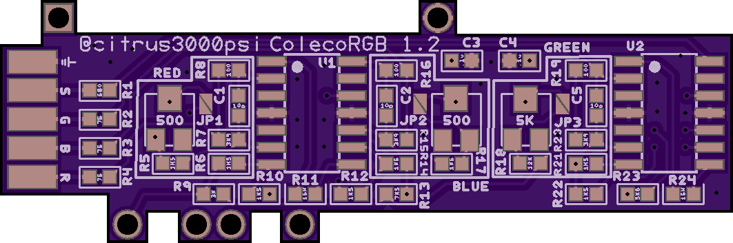
Assembling this board involves some very fine pitch soldering. I've done quite a lot of fine pitch soldering and I still managed to get it put together with a cold solder joint on one of the resistors which prevented me from getting a working C-Sync signal. Give yourself the gift of saving time by following along and checking all of your connections with a multi-meter. OSH Park makes you order a minimum of three boards - you can use one of the extras as a map to trace where everything connects and check that the resistance between components matches the values of the resistors you've installed.
Disassembling the ColecoVision
There's an excellent tutorial on the Retro Consoles Wiki which does a good job of explaining how to get the thing apart. Getting the top off without ruining the metallic sticker across the front can be tricky, but I followed the instructions in the tutorial and had no trouble. Just remember go slowly and don't force anything. It can be stubborn but if you're patient, you'll eventually get it.Removing the RF Box
To keep the install as clean as possible, we'll want to remove the RF box so we have a place to mount the new AV jack.
As retro consoles go, this was by far the easiest time I've ever had removing an RF box. You'll want to start by prying the lid off of the top of the RF box - mine was just held in place with tension, but it's possible you may have to de-solder the ground cable to get it open. Once you have the lid off, flip the motherboard over and de-solder all of the RF box tabs from the underside of the motherboard. On my console at least, the tabs were just soldered in place rather than bent or twisted so they came free easily once the solder was removed. Once the tabs are free, flip the motherboard back over and de-solder the 8-pins of the J4 connector marked in the image below. After that the RF box should just slide off.
As retro consoles go, this was by far the easiest time I've ever had removing an RF box. You'll want to start by prying the lid off of the top of the RF box - mine was just held in place with tension, but it's possible you may have to de-solder the ground cable to get it open. Once you have the lid off, flip the motherboard over and de-solder all of the RF box tabs from the underside of the motherboard. On my console at least, the tabs were just soldered in place rather than bent or twisted so they came free easily once the solder was removed. Once the tabs are free, flip the motherboard back over and de-solder the 8-pins of the J4 connector marked in the image below. After that the RF box should just slide off.
 |
| The RF box with its lid removed. You'll need to de-solder the 8 pins surrounded in red in order to free the RF Box from the top side of the motherboard. Don't mind the extra components and the electrical tape - those are just part of the Ben Heck mod. |
Notes on Installing the Mod Board
The mod board installs directly underneath the TMS chip. It should be the only chip on the motherboard with a heat sink.
 |
| The RGB mod board installs to the underside of the TMS chip, (marked in red) |
Once you've located the TMS chip, flip the motherboard over. You'll want to line up the large holes on the outer edge of the mod board with the TMS pins. The upper-left hole should line up to pin 1 of the TMS chip.
On my particular ColecoVision, the pins at the underside of the TMS chip were not perpendicular to the motherboard. They were all slanted towards the center of the board, and several of the pins had been flattened against the motherboard. I presume this was done to hold the chip in place prior to being soldered at the factory. You can see an example of a flattened pin in the image below, just beneath the R22 resistor on the mod board.
You'll want to straighten any flattened pins which need to connect to the mod board before installing to ensure that everything aligns properly and makes good contact. This is a very old motherboard and very easy to damage if you use too much heat or too much force. Whatever you do, don't try to hurry through this. The way that worked for me was to apply some fresh solder to the flattened pin and use a small flat-bladed precision screwdriver to get under the pin and gently bend it back straight while the solder was molten. If you do it like this, do not try to lever the blade of the screwdriver against the motherboard - try as best as you can to only touch the pin itself with the blade. I went in very small increments, only holding the iron to the pin for three or four seconds at a time and only bending the pin a couple degrees at a time.
You'll want to straighten any flattened pins which need to connect to the mod board before installing to ensure that everything aligns properly and makes good contact. This is a very old motherboard and very easy to damage if you use too much heat or too much force. Whatever you do, don't try to hurry through this. The way that worked for me was to apply some fresh solder to the flattened pin and use a small flat-bladed precision screwdriver to get under the pin and gently bend it back straight while the solder was molten. If you do it like this, do not try to lever the blade of the screwdriver against the motherboard - try as best as you can to only touch the pin itself with the blade. I went in very small increments, only holding the iron to the pin for three or four seconds at a time and only bending the pin a couple degrees at a time.
Note in the image below that snips from component legs were used as jumpers in place of the output resistors, and that I did not attach a wire to ground. We'll pull ground from elsewhere.
 |
| The RGB Mod board installed. |
Wiring the AV Jack
The miniDIN 9 jack has the following signal pins:
- Red
- Green
- Blue
- Sync
- +5v
- Composite Video
- Right Audio
- Left Audio
- Mono Audio
The mod board supplies Red, Green, Blue and Sync, the rest need to be sourced from elsewhere on the motherboard.
+5v
+5v can be pulled from a solder point right next to pin 16 of the same chip -shown in the image below.
+5v can be pulled from a solder point right next to pin 16 of the same chip -shown in the image below.
 |
| This shows a great place to grab +5v which is needed for most RGB cables. Please ignore the pin marked "Audio Mono" - read the note below for a better way to connect audio. |
Composite Video [Updated]
RGB is way better than composite, so why would I go to the trouble to keep composite video? For a couple of reasons. The first is to maintain compatibility with all Genesis 2 cable solutions. Without composite video out, composite Genesis 2 video cables won't work. Also, HD Retrovision, sync-on-composite RGB SCART and (untested) RAD2X all expect to find a composite video signal to pull the sync signal from. But second and more importantly, the ColecoVison Expansion Module #1 (it's basically an Atari 2600 that plugs into the front of your ColecoVision) requires composite video in order to work since the video signal is generated inside the module rather than by the TMS video chip where we're pulling RGB from the ColecoVision.
Remote connecting the RF Box [Updated]
We'll want to connect the composite video pin to the output of a composite video mod. Whether you use Ben Heck's mod or something else, they all rely on the circuitry and the LM1889 chip in the RF box to tap composite video. Since we want the RF box's spot for our AV port, the RF box will need to be re-located.
 |
| Use 8-strand ribbon wire to remote-attach the RF-box - box side. |
 |
| Use 8-strand ribbon wire to remote-attach the RF-box - motherboard side. You _could_ remove the jumper connector and wire directly to the motherboard for a cleaner look but it doesn't really gain you anything to do so. The solder joints may not be pretty, but they're solid. |
 |
| Route the ribbon so that it comes out the gap in the RF shield to the left of the second controller port. The brown wire is composite video routed to come out the gap in the RF shield on the other side of the second controller port. |
 |
| Since the RF box is no longer attached to the motherboard, what used to be its bottom is no longer shielded. I cut out a piece of plastic foam to fit inside the box to act as both an insulator and a flat surface for a strip of copper foil tape to replace the shielding. This may not be strictly necessary, but I figure it can't hurt. |
Audio [Updated]
The ColecoVision only provides monaural sound, but this isn't always supported by modern cables. Rather than connecting the ColecoVision audio output to the mono audio pin on the jack, I shorted the left and right audio together on the breakout board and connected the console audio out to that.
It's a good idea to buffer the audio output with a 10μF 25v capacitor. Connect the capacitor with the cathode (-) going to the audio output pin.
 |
| Bend the legs of a 10μF electrolytic capacitor so it can be installed in-line |
Although audio can be pulled directly from pin 7 of the sound chip (U20) as described in the Ben Heck mod, if you use that point the audio from the ColecoVision Expansion #1 will not be mixed correctly and its volume will come through extremely weak. Instead we want want to pull audio from J4(2). J4 is the junction that originally connected the RF box to the motherboard. Pin 2 is the second pin counting from the rear side of the motherboard.
 |
| The anode (+) side of the capacitor connected to pin 2 of the J4 junction. The cathode (-) side of the capacitor is connected to the audio output. |
Alternate Location for the RF Box
Once the RF box was remote wired, I re-attached the ground braid using Kapton tape (not pictured) rather than re-soldering it, then used some padded double-sided mounting tape to fix it in place to the bottom of the console shell in the spot shown below.
 |
| Alternative internal location for the RF box - placed port-side-up. The second red box shows how the ribbon cable fits in gap in the RF shield to the left of the second controller port. |
 |
| The ground braid from the RF box taped to the RF shield. You _could_ re-solder to get a stronger connection, but it's not really necessary and a major inconvenience if you ever need to take the console apart again. |
Aligning and Mounting the AV Jack
Since the jack is a surface mounted part it will actually need to be oriented upside-down to the way it would be on an actual Sega Genesis.
For this part I recommend you place the motherboard in the bottom of the console housing and use a Genesis AV cable plugged into the jack to get it lined up.

With the jack I purchased (From Console5) I noticed it was sitting too low in the opening if I placed it directly on the PCB, so I used some padded mounting tape to serve the dual purpose of giving it some lift and fixing it in place (link to the actual product above).
 |
| A square of scotch mounting tape gives the jack the correct height and holds it in place well enough for testing. |
Finally after I was happy that the jack was properly aligned to the opening, I used some 22 AWG solid copper wire to give the jack a good strong connection to ground.
 |
| After the jack is aligned and checked, use a 22 AWG wire to attach to ground at the spot indicated. |
The AV jack will need to be secured to the motherboard with hot glue after this point as the mounting tape will definitely not be enough to hold it in place long-term.
At this point the motherboard work should be finished. I used a nylon sleeve to keep the RGBS wires from the mod board looking tidy. [UPDATE] unfortunately the re-inclusion of the RF box makes this a bit less tidy, but function comes before form:)
 |
| [NOTE] Disregard the gray and brown wires pictured - I no longer recommend connecting to those points. Top of the motherboard with the mod and AV jack installed |
Calibrating the Mod
Assuming your RGB cables are properly designed, the mod board should properly set C-Sync output voltage for you, but the R, G and B lines will need to be dialed in, and you'll need an oscilloscope to do it properly.
This video gives a pretty decent primer on how to measure video signals with a scope.
Basically you will want to measure the Vpp for each of the R, G and B lines and turn the corresponding potentiometers on the mod board until they each show the correct value. The value you're calibrating for is different depending on where you measure from. If you measure Vpp direcly from the output of the mod board, you're aiming for 1.4Vpp, if you measure from the output end of the AV cable, then you're aiming for .7Vpp (there should be 75ohm resistors in the cable).
You should always measure C-Sync Vpp from the output end of the AV cable, and you should get around .3Vpp, though anything between .3 and .5 is fine.
Modifying The RF Shields
The RF Shields will need to be modified a little to accommodate the new AV Jack and to make sure they don't pinch the wires coming out of the mod board.
I always try to be as conservative as possible when doing this sort of thing, so I used a fine-tipped marker to outline a cutout to make the opening for the RF socket wide enough to make space for the new AV Jack, then I used a pair of heavy duty cutting pliers to cut away some of the shield. I strongly recommend filing down the edges with a file just to make sure you don't cut yourself or snag anything on the new edge.
 |
| Mark the cutout area where the new AV jack will go. It needs to be squared and just a bit wider and taller than the original opening. |
 |
| Once you've removed the material either with heavy duty cutting pliers or a rotary tool with a cutting wheel, check the alignment. |
FYI - I applied hot glue to the jack before seeing how the modified shield fit so I had to cut away a little of the glue to make room for it.
Next you'll want to make some gaps in the side of the top and bottom shields so they don't pinch the wires from the RGB mod.

Rather than try to actually remove sections of the board, I just put the shields loosely in place and made marks with a fine-tipped marker where the wires would lay, then used my cutting pliers to make two cuts and bend the middle inward as shown in the images below.


Now before you button everything up you may want to consider doing a couple of other maintenance items like rebuilding the power switch, replacing the electrolytic capacitors, installing ESD diodes on the controller ports etc... I performed several of these items while I was in there and I'll touch on some of them below.
When I was ready to close things up, I did not really want to re-solder the ground wires connecting the top and bottom RF shields. Honestly the obsession the engineers had with the ground cables in this console is astonishing. For mine, I simply positioned the cables and attached them to the shield with a strip of Kapton tape.
With it all closed up, it's hard to tell we were ever here :)

Was It Worth It?
 |
| Before |
 |
| After |
 |
| Before |
 |
| After |
Other Mods Performed
Electrolytic Capacitor Replacement
I purchased this kit from Console5.com which had all of the capacitors for the mainboard and all of the components required to rebuild the power supply. They also sell a kit with just the capacitors for the mainboard.The ColecoVision has surprisingly few electrolytic capacitors on its mainboard, but the "RF Box" must be removed in order to get at two of them - one of which is on the RF box itself. Most of the capacitors in my ColecoVision were Nichon which have a reputation for being reliable last a long time. From what I can tell they were all still working fine and would probably have provided decades more service.
The capacitor maps on the Console5 Wiki were decent but they don't account for all of the possible variations. In my case two of the capacitors were different from what was listed on the Wiki diagrams. That's why it's important to check the capacitor values as you remove them to note any differences.
Power Supply Rebuild
The ColecoVision has one of the weirdest power supplies I've ever seen in a retro console. It supplies three different voltages - +12v, +5v and -5v. It was probably fine without needing to be rebuilt, but I was trying to chase down that loss of color problem, and the 12v rail was only putting out a little over 11v so I decided to eliminate that as a possible source of the problem.The massive power brick has to be cut open (I used a Dremel and a plastic cutting wheel) to get at the electronic goodness inside. As careful as I tried to be removing the old capacitors and power regulators, these things have been fatigued by the heat of the regulators over a long period of time and as a result I did manage to damage two of the pads. Fortunately it wasn't difficult to fix these. At first I re-assembled the power brick with electrical tape, and it's a good thing I did because I didn't notice the damaged trace and had to open it back up to fix it. When I was really sure everything was working as it should, I re-sealed the brick with black hot glue.
Power Switch Rebuild
Apparently the large specialty DPDT power switch is a somewhat notorious source of problems for the ColecoVision. Over time the switch contacts wear out or get gunked up and build up resistance. For the most part mine worked okay but if I wiggled or touched the switch the screen would wobble so I knew I wasn't getting good contact.I basically followed this excellent guide from colecovision.dk and it worked beautifully. The switch is now smooth and the power is steady.
ESD Diodes To Protect The Controller Ports
Ever since I accidentally killed the JIO chip on an AV Famicom by inserting a controller while it was on, I've been paranoid about ESD damage to the controller ports. Evidently the ColecoVision, like most of the consoles of its day, doesn't have any protection from this at all.
Maybe it's a real problem, maybe it's superstition, but when I saw these on Console5 I figured they were a little pricey but not as pricey as frying some random chip in my newly modded ColecoVision.
Maybe it's a real problem, maybe it's superstition, but when I saw these on Console5 I figured they were a little pricey but not as pricey as frying some random chip in my newly modded ColecoVision.
To install these I needed to use flush cutters to trim down some component legs that wouldn't let the board sit flush against the motherboard. I also applied fresh solder to the controller port pins and then used a de-soldering wick to pull away most of the solder - also to allow the boards to sit flush with the motherboard. Then I used a length of 22 AWG wire to attach them to ground.


This is a great tutorial. Thanks for writing all of this up.
ReplyDeleteOver in the AtariAge forums (starting in February), we've been testing and breaking down some of the problems in all of the known RGB solutions for the Colecovision to try and fix them. The Citrus board in particular has lots of problems ( https://twitter.com/Mobiusstriptech/status/1255496626845757447 ) with the "pixels are too narrow" issue showing up right in your Donkey Kong picture above. When transitioning from black to any other color, it cuts the front half of the pixel off, so vertical lines (like the ladders in DK) show up really poorly. It can make text very hard to read.
Lots more information (and oscilloscope shots), here: https://atariage.com/forums/topic/274474-new-coleco-rgb-board/?do=findComment&comment=4481888 If you follow that topic for the next 6 or so pages, there is a new ("TMS-RGB") board that solves all the known issues. I've handed a few assembled boards off for final testing before putting up the final information site and OSH Park links. It's got a 5V output right on the board, doesn't require any tuning, and provides both TTL-level and video-level C-sync, so it's a lot more flexible when it comes to output jacks, supporting the "plain" 8-pin mini DIN to SCART solution and things like Genesis 2 RGB cables natively.
It might be worth trying to fix the too-narrow vertical lines problem.
My colecovision works if I have the channel switch in middle of 3 + 4. I am thinking need new RF Box. Would this mod fix this? I think you only need RF for Atari module. I wonder if I can just replace the channel switch. However, not sure where to find something that would work.
ReplyDeleteLike the other switches on the Colecovision, the channel switch internals oxidize over time. The reason your switch needs to be in the middle to work is that the resistance is too high where the contacts normally rest. I have had to rebuild at least one of those ch3-4 switches to bring a console back to life which involves de-soldering the RF box, desoldering the switch from the box, carefully prying the retaining tabs open scrubbing the contact points on the switch with a fiberglass pen, packing it with dielectric grease and re-assembling. It’s a bit of a chore, but it’s just a small scale version of the procedure for rebuilding the power switch, and you WILL need to do that eventually anyway. If you want to try a quicker route, grab a can of deoxit D5 and try to soak the switch with it from the outside. Work it back and forth a bit and see if that gets it to work normally. To answer your other questions, you only need to keep the RF box if you want composite video out and compatibility with the Atari expansion module. If you just want to go straight up RGB then you can remove RF entirely. (But don’t use the RGB mod I show in this post-the newer TMS-RGB Is way better. https://yesterware.blogspot.com/2020/07/tms-rgb-another-colecovison-rgb-video.html?m=1)
DeleteIf you do the composite/RGB mode and have the sega genesis 2 connector what cables do you get for it to work with modern tv's? I seen RAD2x cables but dont think available in USA.
ReplyDeleteWell, if you do the mod exactly the way I did, then literally anything that works with a Genesis 2 will work. You can use regular Composite video cables available on dozens of websites. You can use HD Retrovision Genesis component video cables which you can buy from Castlemania games among other places. You can get RGB SCART cables if you're set up for SCART - I like Insurrection Industries and Retro-Access cables for this. You CAN get RAD2X cables in the US - I live in the US and ordered them directly from retrogamingcables.co.uk - you'll want to get the "Mega Drive 2" cable.
DeleteCan you please explain why you buffer the audio? Thank you!
ReplyDeleteWell I’m not an electrical engineer so I may not be using the correct terminology, but I will give it a shot. When you connect an audio circuit by plugging in a jack it’s hard to know exactly what’s on the other end. The audio device impedance (resistance) may be higher or lower than you’re expecting. Too high and your output circuit will be stressed by having to “push” harder to transmit the signal. Too low and the output chain might actually try to draw too much current which also stresses the audio circuit and can lead to volume drops etc... Plus even if the circuit itself has the correct impedance the act of plugging it in live can cause a voltage spike or ESD. In any of those cases you do not want to drive your audio output directly from the integrated circuit because if you fry that you can’t get a new one. The capacitor acts as a cushion - smoothing our voltage/current spikes and providing a reservoir of energy to handle impedance drops all to avoid stressing the IC that’s generating the audio signal.
DeleteThank you so much! Off to buy capacitors...
Delete