TMS-RGB (another ColecoVison RGB Video Mod & Repair Log)

Why Do We Need Another ColecoVision RGB Solution?
After writing about my experience installing an RGB and Composite Mod in my ColecoVision, I received a couple of comments about how there were "issues" with the mod I had chosen. Despite the fact that I was perfectly happy with it, I did wander over to AtariAge and looked through the years-long discussions taking place about problems with ALL of the existing RGB mods. Most of it became so esoteric and nit-picky that it was difficult to really understand what the real problems were. Then another user (Nicholas Piegdon) commented on my article and took the time to explain one or two of the issues evident in the images I had posted. He also provided a link to a thread on Atari Age about an upcoming project for an RGB mod which addresses some issues which aren't addressed by any of the other mods currently available. This seems to boil down to a couple of issues inherent to the TMS chip which is used by the ColecoVision to generate video. Over the following weeks the project finished testing and was named TMS-RGB.
Does It Really Matter?
In a nutshell there were two issues with the citrus3000psi RGB mod (really all of them, not just that one specifically) that actually mattered to me. Firstly the color blue is rendered wrong. The author of the TMS-RGB describes this as "too much blue". When using the citrus3000psi mod, it was nearly impossible to get it dialed in correctly by "look". By scope it looked correct, and to be forthright it looked "fine" to my eyes. It's only in comparison to the composite video signal that you can really see that the colors are somewhat off. The second issue which I noticed before anyone explained it was the "skinny" vertical lines. I'm not entirely sure that I have the technical explanation correct, but as I understand it when going from black to any color, the first half of the pixel remains black. The result is that 1-pixel-wide vertical lines such as text and the ladders in Donkey Kong appear very thin (there are example images at the bottom of this article). The interesting thing is that I only noticed this on CRTs - when the image is digitized by an OSSC or RAD2X it appears perfectly normal.
The TMS-RGB claims to address these issues and all other issues (which I couldn't really find a concise summary for) with previous RGB mods for the ColecoVision so I decided that I had to give it a shot.
A New ColecoVision Enters the Fray
In order to be able to make direct comparisons, rather than replace the citrus3000psi mod in my original ColecoVision, I decided to purchase another one. I got a fairly decent deal on a "parts or repair" unit.
(If you just want to know about the TMS RGB and not necessarily about the particulars of other repairs and mods performed on this ColecoVision, just skip down to the section titled "Now it's time for RGB".)
Prepping for Greatness
When the new CV arrived from Ebay the first thing I did was to take it apart and vacuum out all of the fuzz and bug guts and fluff and assorted debris. Then I used my air compressor to clear out the controller ports, the cart slot, the RF Box etc...
Once the motherboard was clear of dust and debris, before I even tried to turn it on, I removed and refurbished the power switch, re-flowed the solder on the power wires, and gave the CH3-4 switch, the RF port, and the cartridge slot a good shot of Deoxit. When I connected the RF cable, the power cable, a controller and a game, it fired right up.
Controller Port Repair
 |
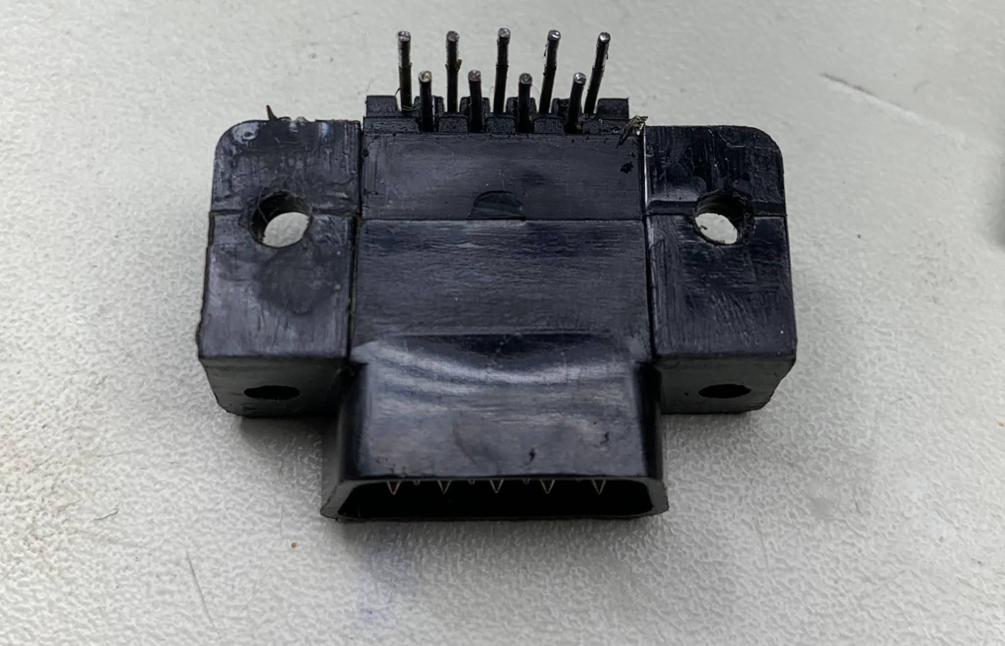
| It was kind of hard to get a good angle to show what was going on, but notice how the controller port isn't sitting flush against the motherboard - it's basically only being held on by the pins which flex and bend quite a lot when inserting and removing the controller plug. |
The controller ports had been abused pretty badly - port 1 was visibly bent so that it wouldn't sit flush with the motherboard and all the stabilization pegs were broken off. Port 2 was still in the right position, but also missing two of the three pegs. I de-soldered port 1 and carefully straightened the pins then put it back so it would sit flush. After giving it a little thought I decided to drill out the landings where the pegs originally were and use zip-ties to secure the ports. It worked better than I expected and now the controller ports don't flex or give at all when plugging and unplugging.
 |
| Controller Port 1 with pins straightened and the landings drilled out |
 |
| Fitting the zip-tie through the newly drilled holes to fasten it to the motherboard |
 |
| Once tightened the zip-tie gives this port better support than it had from the factory. It was so sturdy I did the other port too just for good measure. |
I also noticed that the RF box was a little finicky about having the CH3-4 switch touched and would lose picture when I did so, so I carefully de-soldered, refurbished and replaced it as well.
From there it was time to start modding.
Don't Leave Composite Behind!
Just like before I really wanted to retain the composite video signal, not just for compatibility with all Genesis 2 cables, but also to maintain a level of compatibility with the Expansion Module 1 (which lets you play Atari 2600 games on the ColecoVision). Since the Expansion Module generates its own composite video signal which gets passed into the CV through the expansion slot, you can't use the expansion module with RGB, but it still works great with composite video.
Rather than go with the Ben Heck composite mod, I decided to try out the Mobius Strip Tech Composite Video Mod which I purchased at Console5.com. Unfortunately the mod still requires the presence of the LM1889 chip in the RF Box in order to work. However I found a area just behind the first controller port to mount it. With the RF Box out of the way it was easy to find sources for the video input and VCC nearby.
 |
| With the RF Box out of the way, the Mobius Strip Tech composite mod board nestles snugly behind the first controller port and finds all the signals it needs right nearby. |
I soldered an 8-wire ribbon to the J4 connector and used it to connect the RF Box. This time I used a pin-socket connection so the motherboard could be removed without needing to remove the RF Box.
 |
| Ribbon wires are soldered to the junction that used to connect the RF Box so we can re-locate it. |
 |
| A ribbon cable is attached to the RF Box to keep it connected to the motherboard. |
 |
| The ribbon pins are soldered in the same place as the original junction. |
 |
| A section of foam is cut out and placed in the open side of the RF Box |
 |
| A strip of copper tape is placed across the foam thus completing the "shield" that used to be provided by proximity to the motherboard. Is this necessary? Probably not, but it can't hurt. |
Audio
For audio, I was able to attach the 10uF capacitor to the leg of one of the disc capacitors near the J4 connector (that formerly attached to the RF Box). Audio is buffered by a 10uF capacitor - the other end is connected to both the L and R stereo channels.
 |
| Audio output was tapped at the foot of this ceramic capacitor. |
With all of that connected up, I tested composite video and audio and it looked great (as great as composite can from a ColecoVision) and sounded great. What's more, it worked just fine with the Expansion Module.
Now It's Time for RGB
For the TMS-RGB board, I went the self-assembly route. Nicholas made this MUCH easier to do by providing a ready-made Digi-Key cart. Only one of the parts was out of stock but it was very simple to find a substitute.
Nicholas also provided very nice instructions for assembling the board using a stencil and solder paste, but I just assembled it by hand (like a grown-up :P).
There were also concise instructions on the TMS-RGB website based on what kind of connector/cable you wanted to use for output. In my case I was going with a mini-DIN 9 to match the Genesis 2 port. The board helpfully provides a separate TTL Sync line just for this purpose. The instructions also explained using 0-ohm resistors on the R, G and B lines rather than 75-ohm to match the Genesis output levels. They also say to attach 75-ohm sync line to the composite video pin of the output connector which I, of course, did not do, but this recommendation is fine if you're not going to retain composite video but still want to maintain compatibility with cables that pull sync from the composite video pin.
Once assembled and checked for continuity etc... I prepared the underside of the TMS chip. Just like in my first ColecoVision, some of the pins were folded over and needed to be gently straightened. There were fewer pins folded over in this one, but the tips were partially clipped so I had to use a pair of precision pliers to flatten the tips and break off the bits of metal hanging from when they were only partially cut at the factory.
 |
| These folded pins need to be straightened before installing the TMS-RGB board (well all of them need to be straightened, but these are the most annoying because they require melting the solder while gently prying them up and it's really easy to do damage if you're not careful. |
With the pins straightened, I followed the advice of the designer and put a strip of Kapton tape along the underside of the mod board, then fitted it in place. It was a good deal more finicky about straight pins than the citrus3000psi board which seems to be because the through-holes were smaller.
The solder pads on the TMS-RGB board are opposite to the citrus3000psi board which made it easier to just route the wire up through the openings left by the RF Box and eliminated the need to do so much modification to the RF shields.
 |
| The orientation of the solder-pads on the TMS-RGB make it really easy to route the signals across the board and through the hole left by the RF Box's green support peg. |
 |
| Fully installed, the mod is very low profile |
 |
| This time around I went with the dbElectronics mini-DIN 9 breakout board which is wider than the one I used originally and required I remove more material from the top RF shield to get it to fit. |
 |
| Making sure there's plenty of clearance all around the breakout board. |
 |
| Ready for reassembly. The relocated RF Box is fixed in place with double-sided mounting tape, and the ground braid is re-connected to the RF shield with tape rather than solder because I'm not a masochist. |
The Verdict
How does it look? Well, it definitely fixes the "skinny lines" problem. The image is noticeably brighter, and on the scope I noticed the R, G and B colors being output were much higher than the .7Vpp (closer to 1.2Vpp) even using a cable with 75-ohm resistors in the lines. Is it too bright? Not really. The colors seem to be a much closer match to the composite video which means they're closer to the programmers' intentions.
 |
| This is the Donkey Kong intro screen on the citrus3000psi mod. I just noticed this pic is a bit blurry but you can still make out how narrow the vertical parts of the text are - it's much more pronounced in real life. |
 |
| This is the Donkey Kong intro screen on the TMS-RGB mod - notice how much more well-defined the letters are and how the vertical sections of text are the correct width. |
 |
| This is the Donkey Kong options screen on the citrus3000psi mod. The skinny pixel problem doesn't apply here because the transition is from blue not from black. It's kind of hard to make out but the colors have better saturation and are a bit darker. |
 |
| This is the Donkey Kong Options screen on the TMS-RGB. Notice the whole screen is much brighter than the citrus3000psi mod, but with less saturation so over all contrast is lower. |
 |
| The opening stage of Donkey Kong on citrus3000psi. The colors are clearly very saturated and this is, I believe, a great demonstration of the "too much blue" issue. The pink girders are almost purple, and the white text is clearly shifted blue (although this is harder to recognize without side-by-side comparison) Also note how the "skinny pixel" problem affects the ladders and text. |
 |
| The opening stage of Donkey Kong on the TMS-RGB. The overall image is brighter with the colors being pretty much an exact match for the composite output. The ladders and text all appear normal as they should. |
All things considered I will not hesitate to say TMS-RGB is definitely the better of the two RGB mods and is a profound achievement considering how long people have been "doing it wrong" up until this point. It is more complicated to build and has a higher cost of materials (~$40 vs ~$28 incl. shipping) but it is totally worth the extra cost and effort. (UPDATE: you can buy this board pre-made from Mobius Strip Tech for basically the same as it costs to assemble the citrus3000psi board from scratch) It produces a great looking picture without any calibration or adjustment (no scope needed), but because it's not adjustable, if you think the picture is too bright you'll need a soldering iron and an assortment of resistors to fix it.
HD Retrovision
There is one thing I would be remiss if I didn't provide some counterpoint to this recommendation on the website to avoid using this mod with HDRV cables:
 |
| This doesn't really make sense |
While I don't doubt that Nicholas encountered problems during his testing that led to this recommendation, it is very unlikely that those problems were in any way caused by the HDRV cables themselves unless the testing happened to be conducted using a faulty cable. I'm probably coming across as defending the honor of HDRV, but really it's because the notion that those cables were digitizing or changing colors is nonsense. The translation they do between RGBS and YPbPr is simply a mathematical (not digital) conversion - as the two formats are really just functionally identical ways of expressing the same thing. This makes me think that the conclusion that the HDRV cables are doing something wrong isn't a very scientific one.
But I digress the point I'm trying to make is that HDRV cables can, in fact, work fine with this mod and don't degrade the picture in any way. In my testing the images were identical between HDRV and RGB SCART. Now, my install did deviate in two respects from what was recommended - I pulled 5v directly from a nearby spot on the motherboard, and I connected a legitimate composite video signal to the composite video pin (instead of 75ohm C-Sync) and either of those may have impacted the performance of the HDRV cable as it does have active circuitry driven by 5v and is designed to pull sync information from a composite video signal on the composite video pin. If your setup is based around component video and HDRV you don't need to worry that this mod won't work for you.
Conclusion
I'm not even a really big ColecoVision fan, but I have thoroughly enjoyed working on these machines and seeing the progressive improvement in video now maximized (in my opinion) by the TMS-RGB.
Nicholas has done a tremendous job setting up the website, generating and sharing resources and he made this about as painless as anyone could. People of all skill levels will find everything from DIY instructions to lists of modders to contact if you prefer to have someone else do it for you. He could have very easily kept everything close to the vest and been the only one selling mods that correct for the TMS chip's idiosyncrasies, but instead he chose to make it available to anyone and everyone. Thanks!


One question I have. How do you get the RF Box off of the board? Do you need to or can you just take off the top of the RF Box? Anyway you have pics of that? I heard you need to use low heat. Someone for sure on my coleco tried to take off box or re-soldered it
ReplyDeleteIn order to remove/refurbish the ch3/4 switch you DO need to de-solder the RF box. If that seems too intimidating (no judgement if it does) then you could bypass the switch by just bridging two of the legs with a short wire or a large solder blob. When you remove the cap from the RF box, look at where the switch is and about 1/4 to 1/3 of an inch in from the edge of the RF PCB you should see three soldered pins in a row - that's where the switch is soldered to the underside of the RF PCB. All you would need to do is bridge the middle pin to the pin on either side (don't bridge all three). Just make sure that the switch is set in the same direction as the two pins you decided to bridge.
DeleteBut to answer your question directly, removing the RF box is easy if you have the right tools. I don't have any pics of the process, but it's straightforward enough. The RF box is held to the main Colecovision PCB by four tabs around the edge of the shield that are soldered to the underside, and the 8-pin J4 jumper - that's the green plastic thing in the images above. To get the RF box off, start by de-soldering the four tabs from the underside of the motherboard (they're super-obvious). To de-solder them you should apply some fresh solder, and use either a de-soldering iron or a braid. The couple that I've done have thankfully not had the tabs twisted which made it really easy to de-solder them. After you get the tabs de-soldered, turn the motherboard back over and look for a row of 8 soldered pins to the right side of the RF PCB - de-solder those and the box should pop right off.
Soldering heat is a tricky thing to make a clear recommendation for because it's not just the temperature of the iron, but the ability of it to move heat at a certain rate. If you have a temp-controlled iron, I wouldn't recommend going over 600 degrees Fahrenheit. However the RF box is functionally a heat-sink and it will draw heat out of your tip faster than many irons can replenish it. These PCBs are old and the adhesive that holds the copper to the silicon can only take so much heat before coming apart. They're not super-fragile but you need to be mindful that they weren't designed to be repeatedly soldered and de-soldered. My personal rule when soldering directly to a PCB is that if it takes longer than about 1 second to turn the solder molten then the iron is probably too cold or there's not enough flux. When soldering don't try to force anything - trying to pull a component out before the solder is completely molten can result in pulling the pad off with it. With large metal structures like the RF box, though, you have to be more patient. I usually start with my iron around 600 degrees and give it several seconds (10 or more) to melt before I turn up the heat. When I do, I try to find the lowest temperature that the solder will remain molten while I'm working with it and stick with that.
Hope this helps.
curious where you get the 8 pin header at?
ReplyDeletehttps://oshpark.com/shared_projects/37rGIZ8P
DeleteThe 8 pin header that you connected to RF Box I meant.
DeleteAah. Well, it wasn't a header exactly, but this is what I used:
Deletehttps://www.amazon.com/gp/product/B07RYM1L3Z/ref=ppx_yo_dt_b_asin_title_o05_s00?ie=UTF8&psc=1