
I'm a sucker for the older sprite-based 2D Mario games and when I learned that a prototype of a Super Mario World-esque game called "Mario's Wacky Worlds" for the CDI had surfaced, I knew I had to play it. This was around 13 years ago. I hunted around for a while and found a decent deal on a CDI-220 system bundled with a game controller and a remote.
When my system arrived, I set it up, burned a copy of the prototype to a CD-R and got about 10 minutes of fun poking around the incomplete demo before exhausting it. Next I tried out The 7th Guest which had held my curiosity since being announced as a title in development for the cancelled SNES CD-ROM addon. There was something wrong with the copy I downloaded and I couldn't get the game to work properly. So I took the next reasonable step and bought copies of the "awful" Zelda titles that were released for the system. Those two were good for less than an hour of combined fun so I put the system away and didn't give it much thought until about 7 years ago when I set it up in my new retro area more out of a desire to have a complete set of consoles than out of any particular love for the system.
Greasing the Squeaky Wheel
When I brought the CDI-220 out of storage I encountered the infamous CD Tray squeak. It took me quite some time to figure out how to fix it on my own, but putting a drop of silicone lubricant on the right wheel on the tray loading mechanism did the trick and it hasn't given me any guff since. (Sorry, I wish I had taken pictures of the right one to help save someone some time, but I sadly did not.)
Fixing the Timekeeper...Twice...sort of...
More recently I learned of the timekeeper battery problem, and sure enough my CDI unit was no longer keeping save data after being switched off. Out of foolish laziness I did not want to disassemble my player before ordering a replacement timekeeper chip. After all, disassembling a CDI-220 while not exactly difficult is tedious and time-consuming. I figured that I could get away with just looking up what sort of timekeeper was in the CDI-220 and prepping it so I would only have to open the system once. So I ordered the cheapest Dallas DS1643 I could find and a socket, figuring that the battery would likely be DOA, but I could save myself some time by grinding down the surface of the replacement, removing the dead battery and mounting a socket for a CR2032. I spent the better part of 3 hours carefully grinding off the silicon surface and carefully excising the battery - confirmed that it was basically dead already as expected.
 |
| Dallas DS1643 All ready for a battery socket - too bad it's not the timekeeper chip my CDI actually uses... Don't be like me - open the stupid player before you buy replacement parts. |
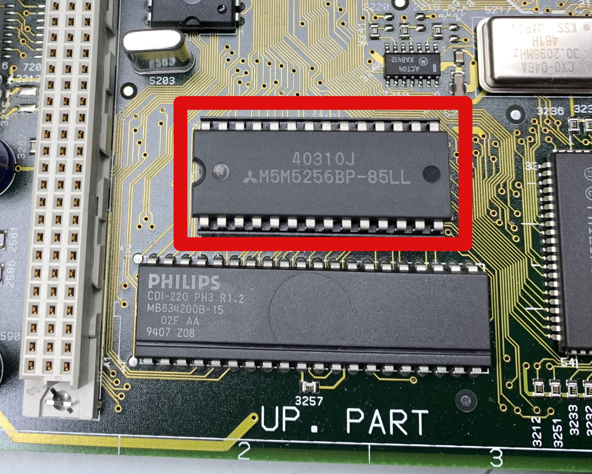
I was all set to mount the battery socket to it when I finally decided to disassemble the CDI and instead of a DS1643, I found a Mitsubishi M5M5256BP RAM chip mounted onto a DALLAS DS1216 chip.
 |
| What the heck is this? This isn't the DALLAS DS1643! Well at least it's already in a socket. |
 |
| Oh wow, that's not just a socket. |
In this configuration the DALLAS chip effectively IS a socket that provides constant power to the Mitsubishi SRAM chip as well as a real time clock. This was a whole different ball of wax. Instead of one battery accessible by grinding off the top of the chip, there were two batteries encased in epoxy inside the bottom of the socket. It's nearly impossible to remove the batteries without damaging the socket. I tried, but it became obvious that the batteries were too close to the wall of the socket to safely remove so I had to settle for just grinding off the strip of metal connecting the battery to the circuit. It's important to do this because if you simply connect a new battery to the timekeeper using the contact points on the top of the socket with the old batteries in circuit, at best the old battery will suck the new batteries dry, and at worst this will cause one or all of them to leak and explode. By drilling in the right spots this is very easy to do.
This video explains where to drill to disconnect the batteries.
Once they were disconnected, I re-sealed the bottom of the socket using hot glue and a strip of Kapton tape to keep the bottom flat so it would sit flush against the motherboard.
 |
| The bottom of the socket sealed in hot glue in case the batteries ever do decide to leak. |
 |
| The Dallas DS1216 socket wired and prepped to be re-installed. Pin 4 of the Dallas DS1216 is 3V. This is both where you'll want to confirm the batteries are successfully disconnected and where you'll want to wire the positive battery terminal. |
 |
| The RAM chip installed back on top of the Dallas DS1216. Now the battery can be wired remotely so if and when it needs to be replaced in the future, I won't need to disassemble the entire CDI to get to it. |
What The Heck, Why Not RGB too?
Round about the time I was working on the timekeeper fix, I also realized that the CDI was about the last of my consoles that did not have RGB output. While the CDI-220 outputs excellent S-Video, having RGB output would mean that I could connect the player via my gScartSW setup which automatically switches between 15 different video sources, and does dual output to both my CRT and OSSC.
Since I had all of the necessary parts on hand already I decided to go for it while the iron was hot, so to speak. I mostly used the Retro RGB guide for reference, but rather than use a generic connector and a generic RGB cable, I modded the console to Sega Genesis 2 specifications. This greatly simplified the mod because the CDI-220 uses the same Sony CXA1145 video chip as the Sega Genesis so all I really had to do was to connect the output lines to this socket using this breakout board. For reference the CXA1145 outputs TTL CSync and color lines are ~1.2Vpp with the expectation that the signal will be attenuated by capacitors and resistors in the cable itself.
Instead of doing a screw-type panel mount socket, I was able to mount the socket flush with the PCB and it aligned perfectly with the bottom opening previously used by the RF module - pretty much identical to the way I did the ColecoVision RGB mods.
 |
| The Genesis 2 AV Multi-Out mounted to the bottom of the two RF Modulator cutouts. |
Composite video and audio were tapped directly from the existing ports so the console is compatible with ANY Genesis 2 compatible cable. I've tested it with HD Retrovision Component cables, RGB SCART, Genesis 2 Stereo AV Composite cables and RAD2X cables.
 |
| RGB Mod installed. Since this is wired to match Sega Genesis 2 cables, the R, G, B, and CSync lines from the CXA1145 are wired directly to the socket (The same way they are on a Sega Genesis console). Audio and composite video for the Genesis cable were tapped directly from the existing ports. |
Fixing the Remote Control
When I bought my CDI, it came bundled with a remote control (specifically a 22ER9055 [RV 7701]), but it did not work. Every time I would start to play with the CDI I would get the remote out and put batteries in it and try to get it working but whatever was wrong was not obvious. This week I finally decided to dive in and figure out what the malfunction was.
The first thing I did was the trick where you point the remote control at a digital camera (such as the one on your phone) and push the button. Because the digital camera can see outside the visible spectrum and shift it, you can see the infrared LEDs flash in the camera. The LEDs weren't flashing on my remote when I pressed the buttons. I wasn't sure that this test was foolproof, and I since I only had the one remote I wasn't sure that the IR receiver on the CDI was working either.
I eventually confirmed that the CDI IR receiver was working by adding it as a device to my Harmony remote from the Harmony database. Took me a while to find it but thanks to a helpful hint from rosewood at retrostuff.org, I discovered that you have to describe it exactly as "CDI220".
So I disassembled the remote, gave it a thorough cleaning, re-flowed all of the components (applied a little fresh solder to make sure nothing had come loose with time or wear). Still nothing.
 |
| RV 7701/00 Remote Control PCB |
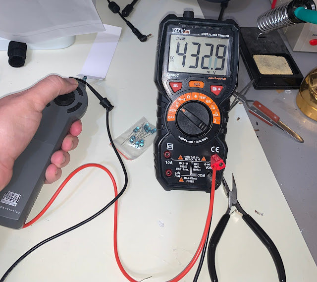
The next thing I did was attach my bench power supply to it. It takes 3 AA batteries so I gave it 4.5VDC and probed various parts of the remote to confirm that the microcontroller was getting power. There were no obvious cracks or open circuits - continuity tests all came back positive. With the power confirmed I used a DMM to do a simple voltage check at the LEDs. I confirmed that when I pressed a button on the remote, the voltage increased at the LEDs, but I still couldn't see any light on camera.
The remote has two LEDs wired in series - meaning they're both powered by the same signal. It seemed next to impossible to me that two IR LEDs could go bad - I figured the problem had to be somewhere else.
Next, I de-soldered and check every other component on the remote's PCB (except the microcontroller which I don't have a way to check and couldn't replace if it WAS bad). The other components checked out fine on my
tester and DMM. When I got to the IR LEDs, they both checked out fine as diodes - they weren't shorted and were allowing current to pass. However they still would not emit light on camera. Based on several recommendations I tried connecting them directly to a 1.5v coin cell battery, then to a 3v coin battery, and finally to a 9v battery with a 470 ohm resistor and neither one of them would light.
 |
| My scribbled notes as I was testing individual components |
Unfortunately there doesn't seem to be a service manual available which covers the components in the remote control so I wasn't sure what a suitable replacement would be. Fortunately IR LEDs seem to be somewhat universal in that they operate in the 940nm band and 5mm is about the only size I could find them in anyway. I ended up ordering
10 of them from Amazon. (Specs described as: Wavelength: 940nm; Emission Distance: 15 Meters / 49Ft; Voltage: DC 1.35V).
 |
| The IR LEDs went bad on this remote. I've noted the polarity of the LEDs in this image as polarity is not marked anywhere on the board. |
When they arrived, I temporarily soldered them to the remote PCB in place of the originals, and I almost couldn't believe it when I saw them light with a button press on the remote. I re-soldered them snugly into the little bracket, re-assembled the remote and tested it on the CDI and voila!
In the process of trying to test the IR LEDs I came across a really cool technique for testing IR LEDs. In my opinion it's considerably less tedious than the digital camera technique in that you don't have to wonder if the trick is working. So what's the technique? Evidently IR LEDs work as both transmitters and receivers - that is to say that if you hit them with IR light they will convert that light into an electrical charge. So you connect a known good IR LED to a digital multi-meter (DMM), then point a remote control at it so that the light from the remote's transmitting LED hits the LED connected to the meter and see if the meter registers a charge.
 |
| One of my new IR LEDs clipped to DMM probes. (Make sure to do a diode test to ensure you've got the polarity right!) |
 |
| Here I have the repaired remote emitter pointed at the IR LED connected to my DMM but I'm not pressing any buttons so it's measuring basically no charge. |
 |
| Hit a button on the repaired remote and the IR LED picks up nearly half a volt of charge from the light the remote is giving off! |
The results of this test were both the coolest thing I've seen all day and impressive. Before I tested this with my newly repaired CDI remote, I grabbed a Sony TV remote to prove that the test worked since that remote is fully working. It DID register but barely charged the IR LED to 100mV. If the charge picked up by the IR LED is proportional to the amount of light being put out, it seems like the new LEDs in my CDI remote are 4x brighter than my Sony remote!
 |
| Aah, that's better! After spending the last 13+ years dead for tax reasons, my RV 7701 is back in action and fully functional. |
 |
| A helpful feature ahead of its time; the CDI lights an indicator on the panel when it's receiving remote control signals! Great for knowing that your remote is working even if nothing is happening on screen. |
I can only speculate as to how both LEDs in the remote went bad and frankly I resisted that conclusion and performed a lot of ultimately unnecessary fault isolation because that seemed too simple to be the problem. Occam's Razor is in full effect on this one.


Comments
Post a Comment