The FM Towns PCs can be a challenge to disassemble because the physical design is very complex and uses a lot of retention clips and pressure fits that will break if you try to remove them out of order. There are a couple of videos on YouTube and some partial guides out there that I used the first time I took one of these apart, but I wanted to make a more complete guide and try to get everything in the best order.
There are several different types of screws involved here so in many cases I made a point to take pictures of the uninstalled screws next to where they go in case you need some help remembering.
It wasn't right to be lazy and say "re-assembly is just these steps in reverse" because that's only about 97% true. There are some steps that are better when done in a different order during re-assembly - these steps are each marked with "re-assembly" notes so be sure to read the words and not just look at the pictures!
The teardown is broken down into three sections:
- Main Chassis and Motherboard
- Power Supply
- Front Panel & CD-ROM Assembly
Tools Needed:
- Cruciform screwdriver (Philips is fine)
- Plastic pry-tool
- Space
- Patience
Recommended:
- Deoxit D5 spray - to hit the electrical connectors during re-assembly to knock any oxidation off and ensure good connections.
Guide Conventions:
- Instructions are oriented relative to looking at the PC head-on, so "right" is relative to the front of the PC - even when dealing with the internals.
Main Chassis and Motherboard
Step 1: Remove the left side panel by sliding down the two retaining clips and tilting outward
Step 2: Use a pry tool to remove the small panel on the top front center to expose the first screw
Step 3: Remove the screw
Step 4: Pull the floppy drive bezel straight forward and out. If this is the first time the machine has been disassembled it may require considerable force. As long as you pull straight outwards you shouldn't break anything.
Step 5: Remove the two screws next to the anchor points for the top handle
Step 6: Press in on this tension clip to free the top panel
Step 7: Remove the top panel by tilting up and pulling forward
Step 8: Remove the Card Slot guide from under the top panel
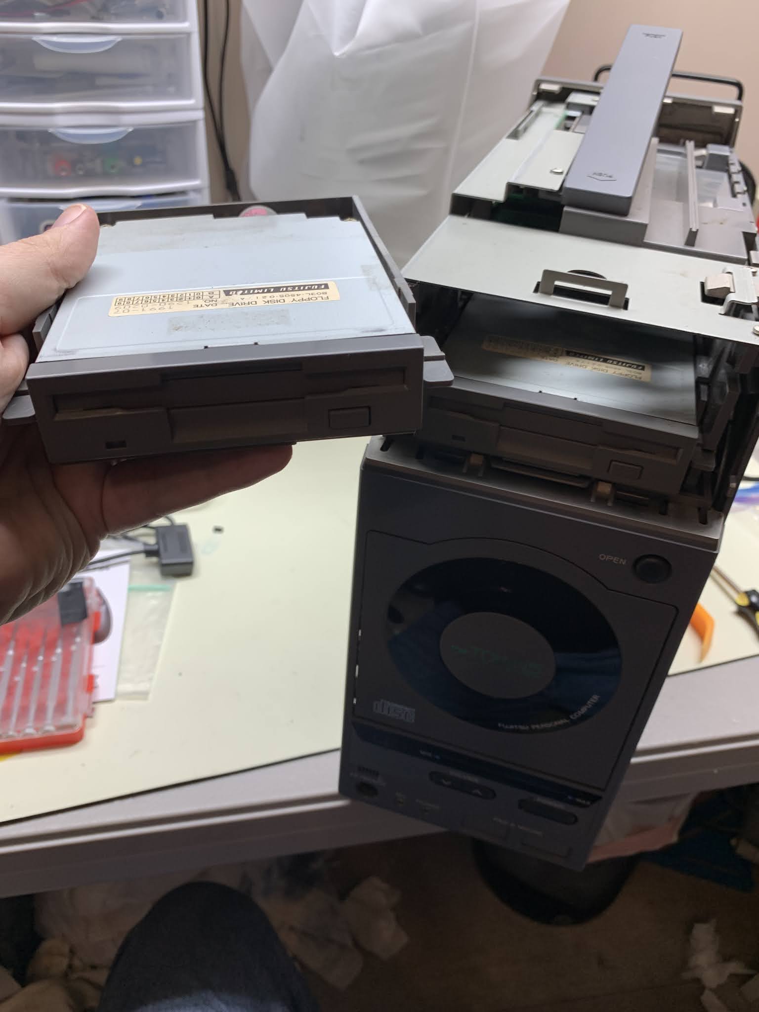
Step 9: Remove the floppy drives by simultaneously pressing down on the tension tabs on either side and pulling straight out. Repeat this process on both drives.
If this is the first time this unit has been disassembled it can take a lot of force to disengage the floppy drives. It's safe to grab them by the tabs, but resist the urge to grab the front of the drive as you may end up pulling the face plate off inadvertently.
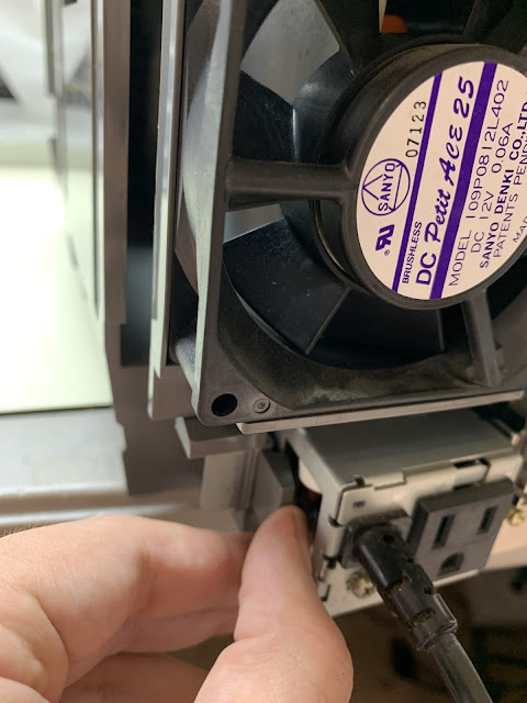
Step 10: Remove the screw holding the front panel and CD Unit in place
Step 11: Release the retaining clip for the front panel by pulling this tab to the left and pull the front panel forward by about 1/2 of an inch. (The panel is still connected by wires and ribbons so do not attempt to remove it completely yet.)
Step 12: Release the ribbon cable clips by grabbing the sides of the white connector and pulling outward away from the PCB. The outer part of the clip should raise and release the ribbon. It should not take any force to pull the ribbon from the connector - if it does not come easily you probably don't have the connector unlocked all the way.
Repeat this for both copper-colored ribbon connectors on the bottom.
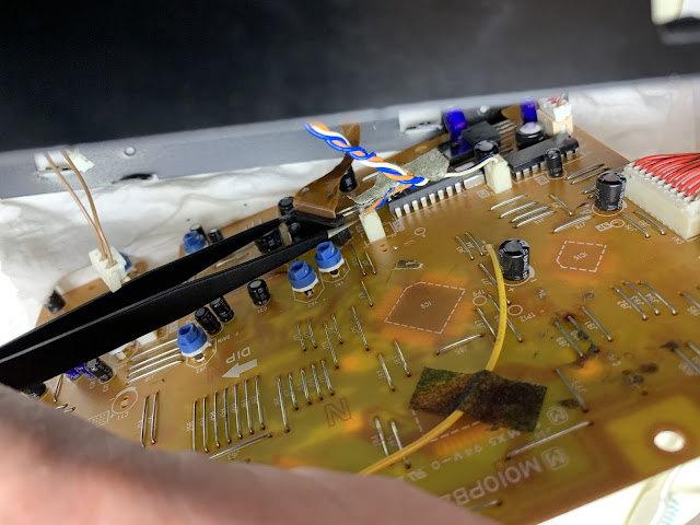
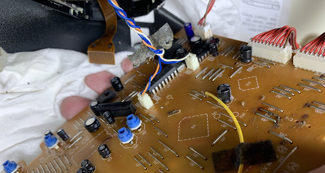
Step 13: Remove the three wire harnesses connecting the front panel by pulling straight out from the PCB. Note the 10-pin connectors are labeled with their connector number, when you re-install take note of which goes where.
Step 14: remove the front panel/CD-ROM unit by pulling straight outward - be careful the plugs like to snag on things on the way out.
The front panel/CD-ROM unit is now separated from the main tower. For instructions on how to disassemble the front panel/CD-ROM unit, see the section below after the main teardown.
Step 15: disconnect the wiring harnesses for the speaker and reset button
Step 16: [Optional] Remove any expansion cover panels from the rear of the PC - these aren't actually attached to anything but the back cover, but removing them may give you more room to maneuver.
Step 17: Remove the rear panel by pressing in and releasing the two retention clips to the left rear then tilting the rear panel outward from the top.
Step 18: Remove the right panel by pressing in and releasing the three retaining clips along the top right edge of the chassis. Note, if this is the first time this unit has been disassembled, the foam speaker gasket on the panel may be stuck to the speaker - just pull slowly to allow time for foam to detach gently.
Step 19: Remove the speaker by pulling straight outward.
Step 20: Remove the four screws securing the metal brackets to the top of the case
Step 21 - Remove the two screws and the bracket from the right side of the case
Step 22: Lay the case down on its right side, then tilt up the metal frame from the top. As it tilts up it should also release the bottom panel in the same motion.
(Note: If you have any RAM chips installed on the motherboard that haven't been removed yet, now is the time to remove them)
Step 23: Sit the chassis upright, and pull the locking tab holding the power supply at the cord/receptacle while simultaneously gripping the power supply receptacle and pulling outward towards the rear of the computer. You should feel the power supply disengage from the interface board. Only pull it back by about an inch for now.
Step 24: Turn the computer back on it's right side, then grip the rear metal bracket and pull the motherboard assembly toward the back of the computer until the connectors disengage from the interface board. Remember there are multiple connectors and if this is the first time you've disassembled the machine it might require a little force to disengage. The interface board should be slightly loose by this point so it can help to push forward on the interface board while pulling back on the motherboard.
Step 25: With the power supply and motherboard both disengaged from the interface board, turn the computer back upright and gripping the power supply and motherboard assembly gently slide them out towards the rear. The retention clip that was holding the power supply to the chassis will get caught on another indentation as you pull it out so you'll need to bend it open again during this process.
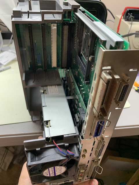
Step 26: release the power supply by lifting the motherboard/audio board up to disengage the bracket.
The power supply is now free from the main unit. Teardown of the power supply itself is depicted in a dedicated section below.
Step 27: pull up to disengage the expansion board from the motherboard
Step 28: remove the two screws from the expansion board to release the metal shield
Step 29: Remove four motherboard screws and the center riser to disengage the motherboard from the audio board.
Step 30: Remove the three screws securing the audio board and the power supply bracket to the rear metal bracket.
Step 31: Remove the power supply bracket. The screws were all unfastened in earlier steps so it should just tip and pull away.
Step 32: Release the motherboard from the rear metal plate by removing the screw posts from the RGB and Parallel ports and the two screws from the SCSI-50 port.
Step 33: Release the audio board from the rear plate by removing the screws from the printer port and gently prying the retention socket from the RCA audio jacks away from the plate. I recommend getting under it with a flat plastic pry tool and slowly working it off so you don't bend the shield.
Step 34: Remove the screw securing the IO board to the audio board then separate the IO board by pulling the mating connector apart.
Step 35: remove the alignment bracket from the I/O board by removing the fastening screw
Step 36: Remove the interface board assembly from the main chassis. Lay the chassis on its left side and the interface board assembly should just lift right out.
Step 37: Place the interface board PCB-side down. Disengage the CMOS battery holder by pinching the sides of holder and pulling out. Unplug the CMOS wiring harness from the interface board.
Step 38: Pull back the three retention clips holding the interface PCB in place. Lift the PCB up from the clipped side and pull out to remove it.
The main 20F Tower has now been completely disassembled. Re-assembly is mostly, but not completely the same steps in reverse. Be sure to read the notes at each step to see which are a little different in reverse.
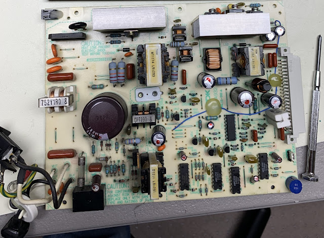
Power Supply
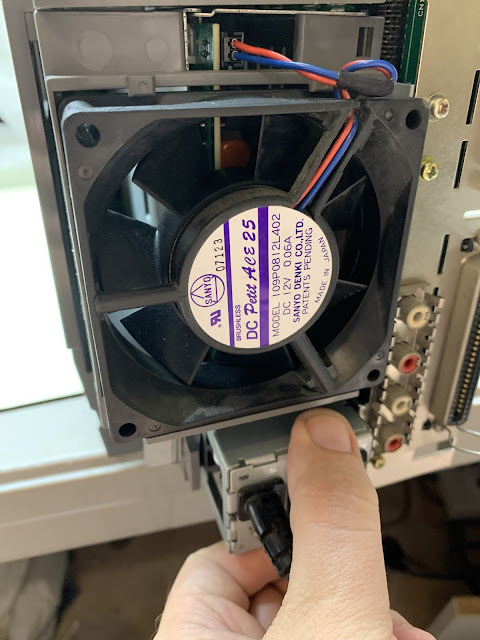
Step 1: Unplug the fan wire harness from the socket by pulling straight forward
Step 2: Remove the fan and fan bracket from the power supply by releasing the tension clips
Step 3: Remove 7 screws from the back plate of the power supply housing
Step 4: Flip the power supply over and remove 2 screws on either side of the power supply socket. These screws are affixed with a thread-locking glue on the other side so it may be best to apply a little heat or use a solvent to weaken the thread locker. Otherwise it will be very difficult to remove them.
Step 5: Flip the power supply back over and lift the back plate off
Step 6: Flip the power supply over to lift the cover.
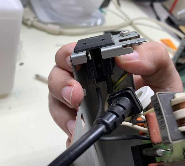
Step 7: Remove the screw to free the ground wire.
Step 8: Pinch the tension clips holding the external power socket together and push the socket out of the bracket to free the power cable and free the power supply PCB/power cable from the power supply cover. (If you find the grounding screw next to the socket is getting in the way of your ability to press the clips in, back it off a few turns to give yourself a little more room to work.)
The power supply should now be fully disassembled.
Front Panel/CD ROM
Step 1: Remove the strip of gaffer's tape holding the front panel ribbons in place. Don't use force - the ribbons are delicate. I recommend using some hot air - either a hair dryer or a hot air workstation on very low heat to soften the adhesive. I like to preserve and re-use the original tape by placing it on a piece of wax paper. If you throw it away, you could get away with electrical tape for re-assembly, but I would recommend using actual gaffer's tape because it lasts longer.
Step 2: Sit the assembly front-side-down. I recommend placing it on something soft to prevent scratching up the front panel or CD-ROM lid. Remove the two screws securing the front panel
Step 3: Press down on the two tension clips on the top of the assembly, then pull straight forward to release the front panel. Reassembly note: It is easier to re-install the front panel if you do it while the CD-ROM door is open.
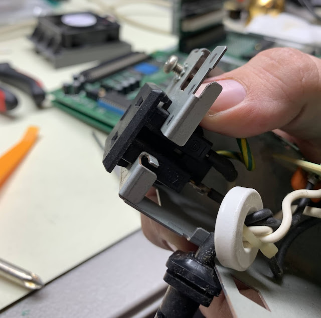
Step 4: With the front panel face-down, remove the screw securing the "PAD & MOUSE" port cage.
Step 5: Release the cage from the front panel by inserting your finger through the port door and pushing the cage back.
Step 6: Remove the four screws securing the CD-ROM drive to the front panel assembly.
Step 7: Lift the front panel assembly frame off of the CD-ROM drive by tilting back. I recommend holding the CD-ROM wiring harnesses in one hand to prevent them from getting caught as you pull the frame away.
Step 8: If they haven't already fallen off, remove the RF shields from the left and right of the CD-ROM assembly.
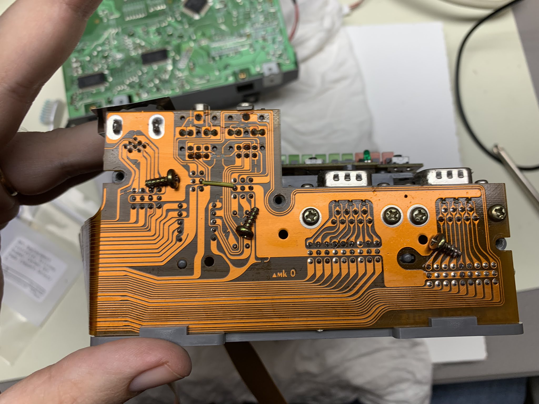
Step 9: Turn the front panel up-side-down. To release the I/O port board remove only the three screws pictured.
Step 10: Remove the front LED panel by pressing down on the two tension clips and tilting outward from the top. Reassembly note: There are two alignment pegs (circled in green) that ensure this panel stays in the correct horizontal position - make sure you have them lined up before you try to push the PCB back into place - since the PCB will flex a little it's possible to do this wrong and you might break a trace in the process. Also, it seems to be easier to reinstall the panel starting with the clip on the right.
Step 11: With the CD-ROM assembly front-side-down, remove the four screws securing the controller board to the CD-ROM housing.
***READ BEFORE PROCEEDING***
CD-ROM Controller Board Removal Cautions:
- Be gentle - there are several attached wires and the CD-ROM ribbon connected to the underside, and none of them have very much slack.
- There are quite a few potentiometers (the little blue things with arrow shaped tops) that you want to avoid accidentally turning. They don't turn very easily but you do need to remain aware at all times of where your hands and tools are when working in these tight spaces - if you do accidentally turn one of them the CD-ROM unit could cease functioning properly.
Step 12: VERY CAREFULLY so as to avoid pulling on the wires or CD-ROM ribbon cable, raise the left edge of the CD-ROM controller PCB. The left edge is the one with the white rectangular label printed towards the edge of the PCB. Use a pair of tweezers to peel the tape holding the CD-ROM spindle and transport motor wires away from the PCB. (This is just to get a little more room to maneuver - the wires themselves will be disconnected in a later step)
Step 13: Disconnect the lid switch wires (double-brown) by pulling straight away from the PCB. I recommend using a pair of very narrow-tipped needle-nose pliers to "walk" the connector off by gently pulling while tilting back and forth. Do not use a lot of force because if your pliers slip you may damage the wire.
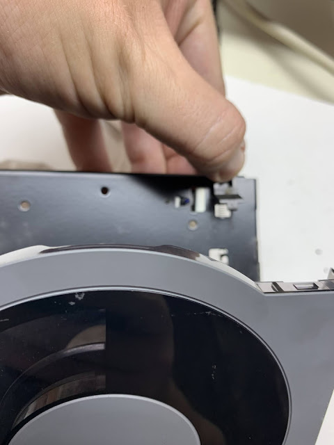
Step 14: Disconnect the CD-ROM limit switch connector (double-white).
Step 15: Unlock the ribbon connector for the CD-ROM drive by pulling up on either edge. A pair of long tweezers works well for this - but again, be careful of those blue pots. Once the connector is unlocked the ribbon should come out with almost no force.
Step 16: Remove the spindle and transport motor power connectors.
Reassembly advice: these connectors aren't keyed so it's possible to mix them up - take note of which goes where - Orange & Blue goes to CN5 and White & Blue goes to CN6. Also when re-assembling it's best to do this step AFTER re-attaching the ribbon cable as it will be much easier to manipulate the ribbon cable into position without these connected.
Step 17: Remove the grounding screw from the laser/spindle assembly and disconnect the ground wire. Because it is so small and easy to lose, I recommend re-installing the screw after removing the wire.
Step 18: Remove the four screws from the shock dampeners around the laser/spindle assembly.
Step 19: remove the laser/spindle assembly from the drive by pulling straight out. The magnetic spindle clamp is holding the laser/spindle assembly to the drive door. You can either use a little force to pull the laser/spindle assembly away from the drive, or you can pull the catch to open the drive door which will disengage the magnet - if you lift up the drive to open the door, make sure you hold the laser/spindle assembly in place with your hand so it doesn't just fall out when the door opens.
 |
| Alternative step - just make sure you're holding the laser/spindle assembly in place so it doesn't fall out when you do this. |
That is as far as this teardown of the front panel/CD-ROM drive is going for the time being. The laser/spindle assembly can be further broken down for cleaning and re-lubrication but that's not in scope for what I'm doing here. The drive door is held in place with C-clips that are very difficult to remove without causing damage.


Comments
Post a Comment