Cassette Players and Sony TC-KA3ES Repair Log

The Principle of Playback
The playback head of a cassette player works on almost exactly the same principal as a record player cartridge. The motion of a magnet across a coil is used to generate alternating current. In the case of a record player, the movement of a stylus as it travels through the groove provides the physical motion of the magnet and coil to generate the electrical waveform - the shape of the groove determines how much or how little movement happens and that variance creates the waveform that is amplified to produce the sound. In the case of magnetic tape, the tape itself is the magnet moving over a coil inside the tape head, and the waveform is generated based on the varying strength of the magnetic flux at any given position on the tape.
The Principle of Recording
To record something onto a magnetic tape, you basically reverse the process of playback. Instead of "listening" to an AC waveform picked up by the coil as the tape moves past the head, you electrify the coil with an AC waveform which imprints on the tape as it moves past the head. In this sense, the playback head of most magnetic tape devices perform double-duty, both recording and playing back signals depending on the direction of the current.
Technically you could both play and record magnetic tape with a single head, however you would only ever be able to record on blank tape. Things get messy once the tape has a magnetic imprint on it - trying to put a magnetic imprint on a tape that already has a magnetic imprint is going to have the magnetic fields competing with each other - and at best you're going to end up with elements of the previous imprint and the new one you're trying to make. It's for this reason that every magnetic tape recording device has at least two separate heads - a playback/record head, and an erase head. The erase head also includes a coil but instead of a sophisticated waveform, it creates a uniform field that demagnetizes the tracks just before they're about to be recorded onto.
Compact Cassette
The proper name for the format we're talking about here is "Compact Cassette", though I never once heard anyone call it that growing up. We either called them cassette tapes, or if we wanted to sound sophisticated, "audio cassettes". In order to impart some idea of how precise and sensitive the equipment needs to be to properly record and reproduce sound with this format, it's important to establish a little about how it works.
There are (have been?) many different commercially used magnetic tape formats which can vary quite a bit from one to another. They all work on the principle of the motion of magnetic tape relative to a coil producing an electrical current, however they don't all do it the same way. Most analog audio tape is linear - that is to say that the magnetic imprints are made in a straight line as the tape passes over the coil. This includes formats like open reel (reel-to-reel), 8-track, compact cassette, micro cassette etc... Helical formats like Betamax, VHS, and DAT, which require higher frequency signals, place their head coils on a drum which spins to perform diagonal passes over the tape as it's threaded through the mechanism. (Technically helical scanning formats are hybrids as they usually also include linear tracks as well).
You probably already understand what I mean by "tracks" but I'd still like to go over the basic idea. Since humans normally have two ears and our brains are designed to extrapolate some sense of position based on hearing two slightly different versions of the sound around us, we like to have our music in stereo - that means that for every single interval of music, we need two separate magnetic imprints on the tape. And because we would rather not have to always rewind the tape back to the beginning after we've listened to the whole thing, we want to record music on both "sides" of the tape. Compact cassette uses 1/4 inch wide tape which consists of four separate tracks: Side A Left, Side A Right, Side B Left and Side B Right. If we break that down a little further, it means that each track must exist within a space 1/16th of an inch wide. This doesn't mean that all 1/16th of an inch is available either - if you think about it like lanes on a highway, if your car took up the whole width of the lane, there would be collisions all the time. You need some space between the magnetic imprints to stop them from messing with each other. So the actual width of the impression is somewhat less than 1/16th of an inch wide. This is why things like azimuth are so key to getting the best out of your cassette playback.
Azimuth
Azimuth is the relative parallelism of the head to the travel of the tape. Since you're reading two tracks simultaneously at any given time, it's important to make sure that the coils are aligned exactly parallel to the tracks. If they aren't you'll lose high-frequency response, and the audio will be out of phase.
Capstans, My Capstans
What moves the tape across the head in a magnetic tape player? If you thought it was the spindles that turn the reels, you would be mostly incorrect. The take-up reel does pull on the tape, but that's just to provide tension and make sure it gets wound properly onto the take-up reel. Turning the reels is not a reliable way of moving tape at a consistent rate. The reels aren't a very accurate mechanism - they have to be loose enough for the spindles to slot in, as the tape tightens or loosens, it slips etc... But perhaps the largest obstacle is that as tape is transferred from the supply reel to the take-up reel, the circumference of the take-up reel gets larger so it pulls in a greater length of tape with every revolution. Even if you could tighten all the tolerances to make the tape reels move at a constant rate, the tape would still speed up as you got to the end.
To move the tape across the head at a constant, correct rate a capstan is used. A capstan is a spinning metal shaft located on the take-up side of the tape head(s). When the mechanism is in the playback position, the capstan is pressed into a rubber "pinch" roller and pulls the tape across the tape head.
The vast majority of compact cassette playback mechanisms only have a single capstan. Many "auto-reverse" mechanisms have two capstans but only use one of them at a time, depending on the direction of playback. These systems expect that the resistance from the supply reel is enough to keep the tape straight and even as it moves past the head. However, some higher-end players employ a "dual capstan" design where a capstan and pinch roller is also located on the supply side, creating a carefully controlled amount of tension as the tape passes the head.
2-head vs 3-head
As discussed above, to record and play audio from a compact cassette you need a minimum of two heads - a double-duty record/playback head and an erase head. Where does the third head come in? The record/playback head performing double duty is a bit of a compromise. The optimum placement and construction of the head coils are slightly different for each function, so two-head systems kind of aim in the middle. But by replacing the combination record/playback head with a single-duty playback and single-duty record head, you can eliminate the compromise.
Three head cassette decks are all unidirectional - that is to say they only play the cassette in one direction. For the vast majority of them this means that you have to physically flip the cassette to play the other side. The only exception I'm aware of is the Nakamichi RX-505 which physically flips the cassette for you.
TC-KA3ES Repair Log
The Sony TC-KA3ES is a 3-head dual-capstan cassette player. I wanted to compare it's performance with my Nakamichi RX-505, but I didn't want to spend a lot so I bought a junk unit off of Ebay to see if I could get it working again.
The unit I bought had two major issues and a couple of minor ones. The first was the that one end of the cassette holder had been shattered, and the second was that it made a horrible screeching noise whenever it tried to put the head assembly into playback position.
The Cassette Holder
The Sony TC-KA*ES line of cassette players have a "cassette stabilizer" built into the cassette holder. When the door is closed the stabilizer is pulled forward into the mechanism and hugs the cassette to prevent vibration of the cassette case during playback. According to the service manual the part number for the cassette holder is "X-3369-639-1".
Before buying the deck, I did a search and found one place on the Internet that claimed to have this part available - Fixpart.be. If I could get the part, the repair might be pretty easy, so I took a risk and bought the broken unit from Ebay. Unfortunately Fixpart only ships within Europe so I had to reach out to a friend in the UK to serve as a proxy for me. Although I was able to place an order, I was dubious about whether they actually had the part, so I went ahead and started trying to rebuild it while I waited. Fixpart contacted me a little over a week later to let me know that they didn't actually have the part.
 |
| Here you can see the broken cassette holder slot. No idea what could have caused this. |
 |
| Here's another shot showing the holder missing the left "wing". You can also see the small gray circle where the peg for the stabilizer cam used to be. Fortunately the two halves of the cam, and the springs were all still present, so it was able to be salvaged. |
The left side of the cassette holder had shattered into about four pieces. I was able to find all but one of the bits down inside the mechanism. The cassette holder has a couple of springs and cam mechanisms on either side right where the holder was broken, but thankfully all of them were still present when I got to it. The holder itself consists of a plastic part and a metal hinge bracket that the plastic part is pressure-fit into. To begin the repair, I had to separate the metal hinge bracket.
 |
| This metal hinge bracket is in the way of repairing the broken holder, so it had to be removed. Re-installation required that I bend one of the sides outward and then back because the plastic part of the holder is pressure fit and I didn't trust the repair to flex that much. |
The plastic the holder is made from is not affected by acetone-based glues, so I had to resort to a binary epoxy (Devcon Plastic Welder). This also turned out to be a good way to rebuild the missing chunk. In order to get the epoxy to take the shape of the missing segment, I used a strip of copper foil tape, both because it would hold its shape and because it was not going to be damaged or deformed by the action of the epoxy curing. There's a groove on the inside of the segment for holding a metal strip that functions as a spring to hold the cassette stabilizer. Rather than try to grind or cut it out after the fact, I used a portion of the epoxy mixing stick pressed into the epoxy when it started to firm up - this beautifully created the shape I needed.
 |
| Here you can see where I placed the copper tape. It served as a "shelf" to build up the epoxy material to serve in place of the missing plastic chunk. |
 |
| Epoxy was used to reconnect the plastic parts, and to outright replace the middle support. This is a shot of the repair in progress. I sanded and cleaned it up better than this before installing. |
The cams on the left and right side of the holder and help the stabilizer move in and out swivel on a plastic peg at the top of the holder. The peg on the left side had broken off and was missing. For this I drilled out the area underneath the peg and drove a narrow screw wrapped in plumbers tape into the place of the plastic peg. It swivels just as smoothly as the plastic peg.
Reassembly was a bit tricky because the plastic holder is supposed to be a pressure fit into the metal hinge bracket. While the plastic welded repair is pretty strong, I didn't want to risk trying to flex it into place, so instead, I carefully bent one of the ends of the metal hinge outward, reinstalled the plastic holder and carefully bent the end back into place.
Once reassembled, the mechanized cassette door works exactly like it should again.
Mechanism Screech In Playback Position
Fast Forward and Rewind functions seemed to work normally, but pressing pause or play would raise the head assembly into playback position, but it the mechanism screeched for a second and then lowered back down. This turned out to be a bad mode motor belt that was starting to turn to jelly. It wasn't loose at all, but it had lost its elasticity so once any pressure was put on it it would squeal as it slipped in the pulley. Part of the noise was also possibly due to failing lubrication on the motors shafts.
Disassembling the mechanism is something to do reluctantly because reassembly requires special tools to get the alignment of the dual-capstan setup correct. At a minimum you need a "mirror cassette" to properly adjust the supply side pinch roller/guide after it's reinstalled.
I thought I could get away with just marking the adjustment nut on the pinch roller, and returning it to the same exact position, but that was based on the faulty assumption that it was aligned properly to begin with, which it was not. The guide on the supply side roller was covered in little brown tape slivers which I can imagine came from the edges of the tape rubbing against the guide walls rather than between them. This thing damaged a lot of tapes before I got it, I think.
Not only do you have to have a mirror cassette to properly re-install the supply roller, you should probably use one to check any dual-capstan machine before you start using it - that position is held by a spring that can lose tension over time, and a misalignment can absolutely damage your tapes.
Unfortunately, the procedure to change and/or check the mode belt is to disassemble most of the mechanism, including the supply side pinch roller. There is a way to change the belt without disassembly, but because I wasn't quite sure what the problem was, and I wanted to lubricate the motor shafts for good measure, I went ahead and tore it all down.
The motors did feel a little "gritty" when turning, and smoothed out with a drop of lubricant on the spindle bearings.
The TC-KA3ES uses the same mechanism (TCM-200) as many other Sony decks, and this video about a later model does a great job illustrating the whole process for this one.
Dirty Dolby Selector
This deck uses a 4-pole rotary switch to select between the different Dolby modes. I noticed when turning it, that the display would erratically bounce between two modes for a moment. While I don't know if this is a typical problem for this kind of deck, it is a problem with rotary switches in general and it's not too hard to fix provided the switch is just dirty and not damaged.
Getting the front cover off required disconnecting most of the wire bundles, some of which are routed almost all the way around the chassis. Definitely take pictures as you do this so things can get put back where they belong when you're done.
 |
| This is a shot of the front panel. The overlapping PCBs on the left are a bit annoying to remove. |
After getting the front panel off, and detaching the PCB that held the Dolby switch, I de-soldered the switch, bent the retention tabs outward and pulled the switch apart. Just as I expected, the inside of the switch was filthy. I used a combination of Deoxit D05 and a fiberglass pen to clean up the contact plate and wiper, then treated both with some Deoxit D100 and finally packed the switch with dielectric grease. The switch is basically sealed, so the most likely source of the black gunk is carbon from sparking inside the switch as the dial is turned. The dielectric grease acts as an insulator which should prevent sparking and make the switch last that much longer between cleanings.
 |
 |
| To get this switch open, you have to bend back the prongs holding the housing in place. The one on the left is already bent back, the one on the right is still in place. I used a small set of needle-nose pliers to do this. Just be careful and patient. |
 |
| The interior of the switch is darkened and discolored with what looks like oxidation. |
 |
| After cleanup with Deoxit D05, a fiberglass pen, it's treated with Deoxit D100 then packed with dielectric grease to minimize oxidation and reduce the possibility of sparking causing carbon buildup |
Reassembly
Cleaning and Conditioning the Pinch Rollers
While I had everything apart, I noticed that the erase head was very visibly streaked with tape residue - probably worse than anything I had ever seen. It's not surprising, though, as the erase head is used to set "thrust" as the service manual calls it.
The manual says you can clean things with isopropyl alcohol, but I prefer to stay away from that as it's not really great for rubber or plastic parts. I'm a fan of Audio 456 cleaners which you can get here.
The tape head and capstan cleaner was used on all the metal parts in the tape path, including scrubbing the gunk off of the erase head.
The roller cleaner and rejuvenator did a great job resurfacing the rollers. You can get cheap aftermarket replacements for these, but from what I've read they usually result in worse wow and flutter than just fixing up the old ones, so I wanted to see where I got just cleaning them up first.
Checking Alignment/Making A Mirror Cassette
 |
| The mirror cassette completed |
This was already touched on above, but it's important enough that it bears repeating - a mirror cassette is not optional for dual-capstan machine owners. Single capstan machines usually have fixed alignment paths, but the additional of a second capstan on the supply side which creates tension across the tape path makes it necessary to introduce a guide, which of course needs to be aligned properly so that the tape passes parallel across the playback section.
Once upon a time, according to the Internet, mirror alignment cassettes were something you could pick up professionally made for around $20. Nowadays I couldn't find one that anyone was willing to part with for less than $100. So, after watching a couple of videos and looking at some images of mirror cassettes, I bought an $8 pack of tapes and a $10 pack of acrylic safety mirrors and set about making my own.
The process is:
- Remove enough tape that the reel doesn't cross below the interface trapezoid
- Separate the cassette shell - consider the side with the screws the "front"

- Remove and set aside the tape reels, rollers, and static guards

- Cut away the trapezoidal "mouth" part of the shell from the front
- Cut away the guide posts in the center of the "mouth" on the back side of the shell (to make space for the mirror), but do not cut away the flat sections at the "bottom" from the back.

- Position a 61mm x 10.5mm mirror at a 45 degree angle with the bottom resting just above the capstan holes on the back part of the shell and the top resting against the top of the cutout area
 |
| When checking fitment, while looking straight on, you want the ridges on the bottom half of the shell to come to end in the center of the mirror. This will ensure that the tape path is fully visible when inserted into the machine. It doesn't have to be perfect, but you want to get it as close as possible because your viewing angle through the cassette holder is limited. |
- Check the mirror position and make sure that when looking straight on, the flat sections at the bottom of the case appear in the vertical center of the mirror.
- Once aligned, affix the mirror with hot glue.
- Re-install the static guards, the reels and rollers
- Check that the tape moves normally.
To align the tape path, put the mirror cassette in, and start playing it. Make sure the tape travels centered on both the erase and playback heads, and that it isn't curling at either side.
 |
| You want to make sure that the tape path is perfectly centered on the erase head - when it is, everything else will be perfectly aligned as well. |
Wow and Flutter
Wow and flutter is the term used to describe the variation in playback speed of analog audio devices. It's usually caused by the stretch and gather of belts, worn rubber parts, or simple imperfections in the design.
Alex Freed makes and shares a small program for measuring wow and flutter called WFGUI. You can get it here. This eliminates the need to have a standalone piece of equipment to do this measurement.
Use a stereo RCA to phono adapter and plug the deck into the microphone port of a PC or laptop, insert your 3kHz or 3.15kHz test cassette and hit play. When you start WFGUI and set it to listen to your microphone, it'll give you a readout telling you what the wow and flutter percentage is.

The values I pulled were between .05 and .07% which is a little on the high side for this deck. I've ordered new belts and rollers to see if there's any improvement to be had.
Checking/Adjusting Azimuth
Although the azimuth adjustment screws are usually fixed in place with a locking compound after being set at the factory, they still somehow get out of whack over time. I guess maybe the spring that pushes against the screw loses tension over time?
With the deck audio outputs connected to an oscilloscope, turn off Dolby NR, and playback a 10kHz test cassette. The higher frequency allows for finer adjustment.
The waveforms for left and right should show the same amplitude, and perfectly overlap one another if azimuth is correct. In my case the two sides were almost 180 degrees out of phase to start with. The azimuth adjustment screw is recessed so far that none of my existing non-magenetic screwdrivers could reach it. I had to go to the hardware store and buy a #0 philips screwdriver to get at it.
After the tiniest of tweaks, the waveforms lined up perfectly.
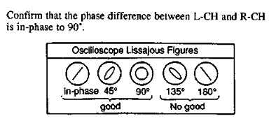 |
| The service manual describes anything from perfectly in-phase to 90 degrees as within spec. |
Lastly I used my scope's X-Y time series mode to plot a Lissajous figure and confirm that the left and right are nearly perfectly in-phase.
Setting Output Levels
It's very important to do this AFTER you've set the azimuth correctly because a bad azimuth can cause uneven volume between the left and right channels. If you set levels beforehand it can mask a problem with azimuth or make it more difficult to dial it in. So, azimuth first, output levels after.
A 315Hz test tape was used to provide a constant tone to set the levels by. The service manual describes the use of a VTVM - a vacuum-tube voltmeter with a 47kOhm resistor in series then dialing output to a particular mV range. I'm not sure that I care that much that the output is at exactly the right level. What I do care about is having the two channels amplified at equal volumes, so I used my scope and just made sure that the wave amplitude was the same for both channels.
Screws
The previous owner, or I should say one of the previous owners removed all of the chassis screws and didn't put them back. When I received the deck only 3 of the 10 screw holes were populated and those had obviously wrong-sized screws that were a major pain to get out. I spent an embarrassing amount of time looking for information on what kind of screws to replace them with before discovering that the chassis screw sizes are actually documented in the service manual. I was able to order a package of black M3x8 screws which were nearly perfect replacements. Unfortunately four out of the six screw holes on the top had been ruined by someone forcing too-large screws into them. The screw holes are punch-outs so I was able to somewhat reshape them by pinching the punched-out portion with a pair of needle nosed pliers. It's not a perfect solution, but it works well enough.
Conclusion
With the deck all put back together and tuned up I was finally able to pop in some tapes and give them a listen. While it's definitely a high fidelity deck and I still have one or two things to do to dial it in, this was enough to get a feel for it. The Dolby performance is way above what you normally get with cheaper decks - it suppresses the noise without completely killing the fine detail. The Nakamichi RX-505 still beats it, though it's hard to quantify the difference. The Nakamichi just doesn't sound as "harsh", and the Dolby noise reduction is noticeably better at leaving detail intact.


Comments
Post a Comment